• Welcome to the Contour Enthusiasts Group, the best resource for the Ford Contour and Mercury Mystique.

    You can register to join the community.

RWD CSVT: PRT's CDW-27 RWD conversion build thread.

I'm sorry it's taken me so long to find time but I've finally found time to make real updates.

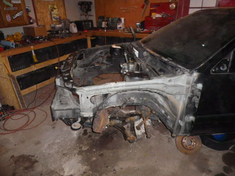
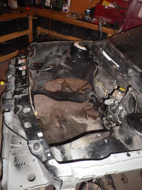
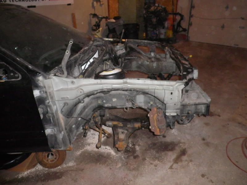
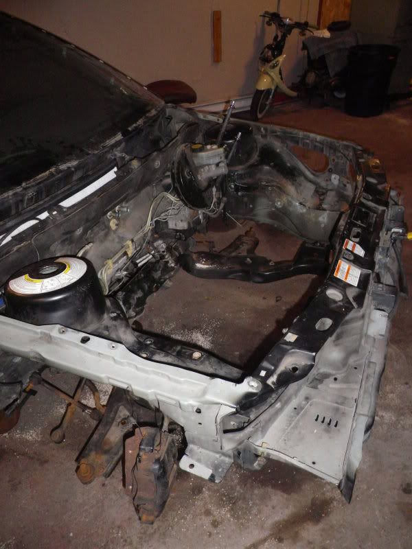
As stated earlier I got a Black E0 from Blu_fuz. The car had a rod knock and he and another member had begun to part the car out. Then I came along and took the car as it sat, It had no suspension or wheels so I brought what we needed, set her on the ground and I puller her home. Initially I had intended to use the car to build myself a new DD, so after pulled the blown stock unit, I dropped in an SE motor I had laying around, added a COP swap and built trans with headers and spec stage 1. Not long after I dropped the motor in I got a new shop with heat, so we moved the car out there and I continued assembly there, cleaning the interior, repairing wiring and replacing all the components that were missing with items from my stock of spares. As you can see the interior was a mess. All of the seats were damaged and the front doors gutted. I cleaned the interior up, installed a dash and harness and finished engine assembly. We fired the car up after just a couple days and once I got it back to running condition I decided given the car's overall minimal rust that it would make a good candidate for the RWD conversion project's final home, and with that I decided to pull the new heart right back out.

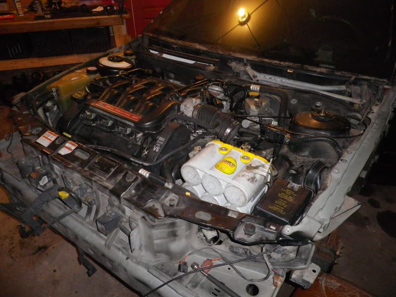
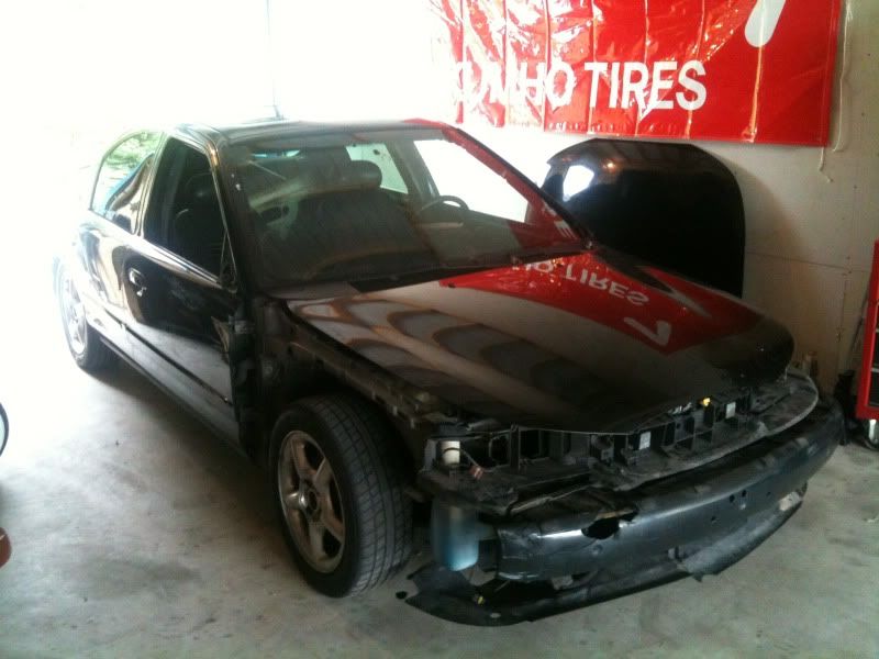
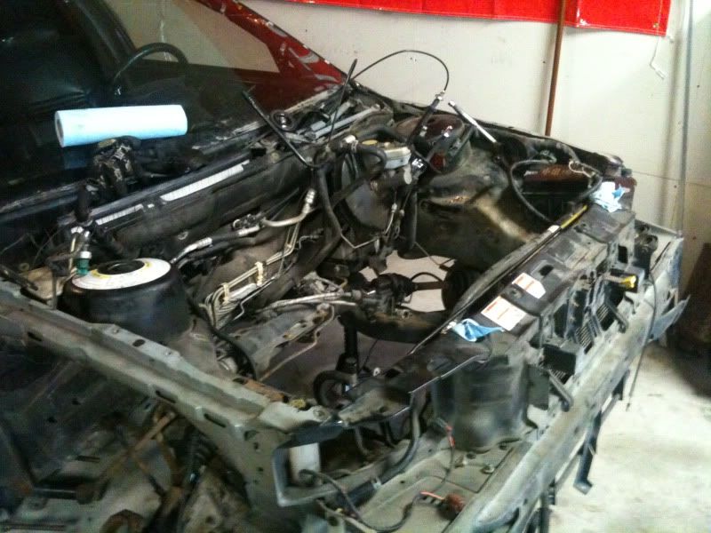
The car as I towed it home:

IMG_0854.jpg


IMG_0865.jpg


IMG_0872.jpg


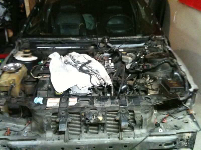
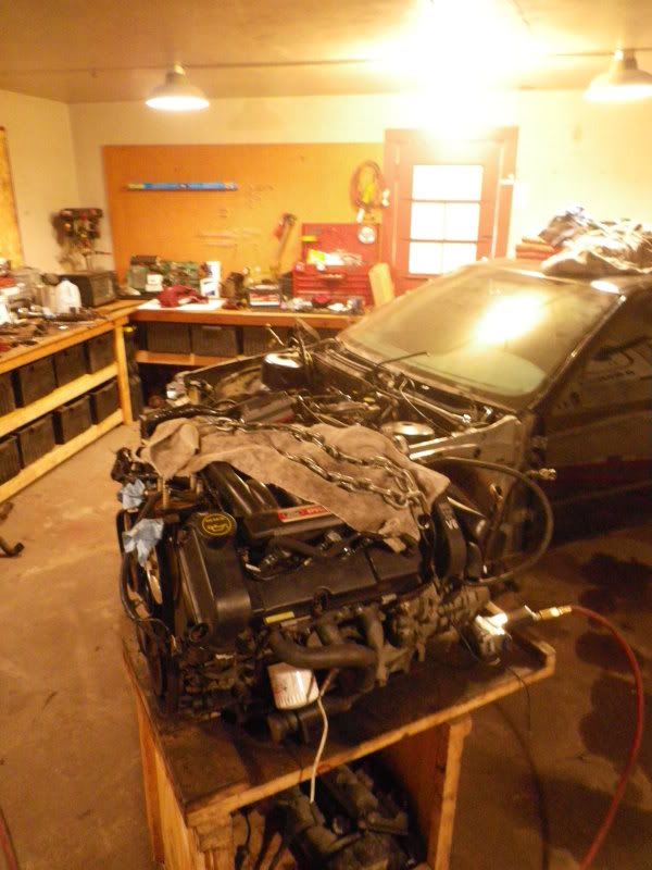
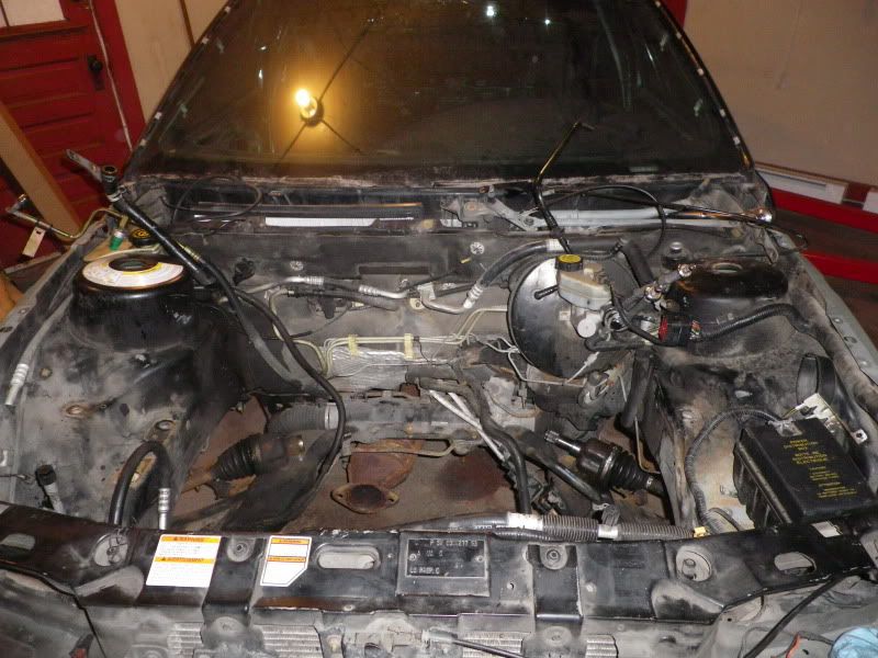
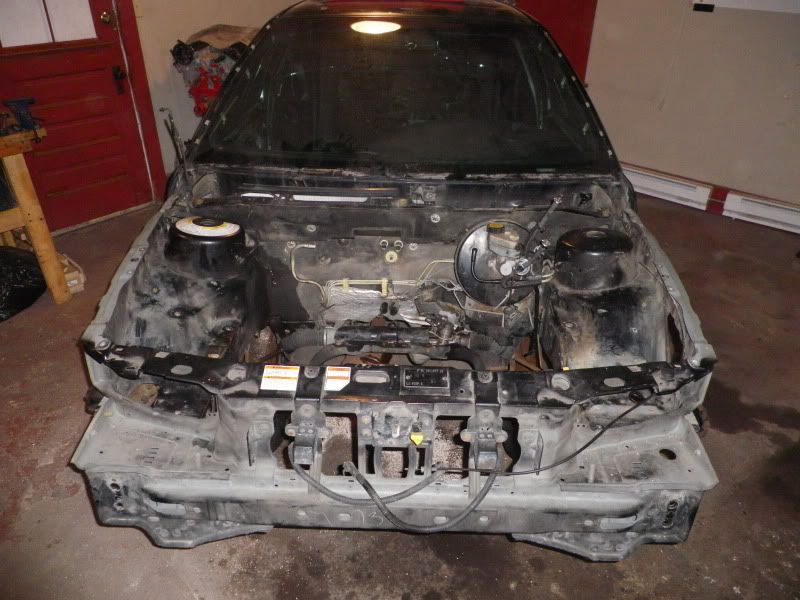
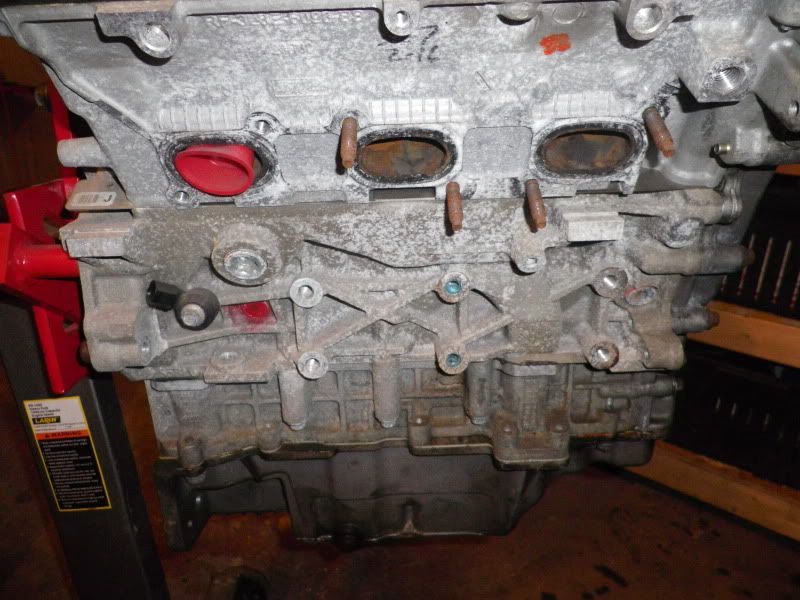
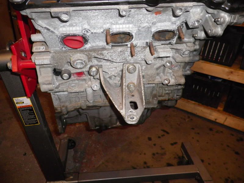
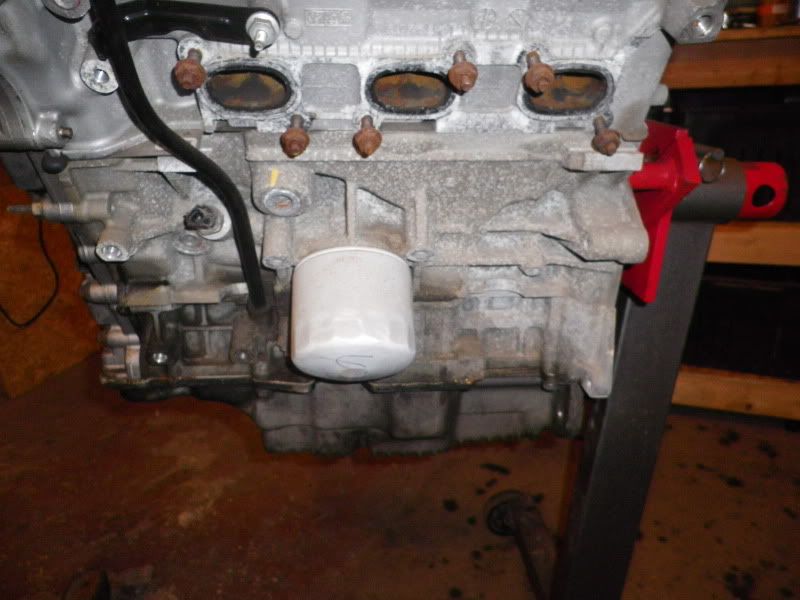
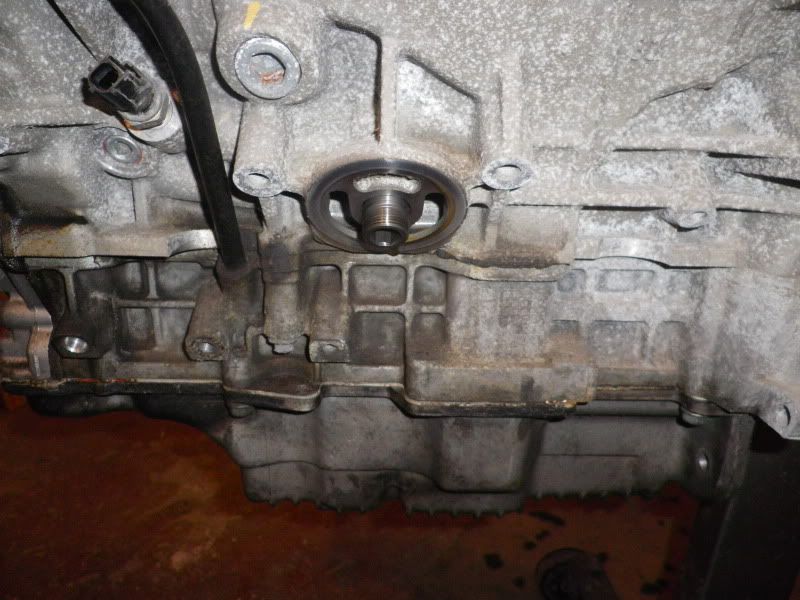
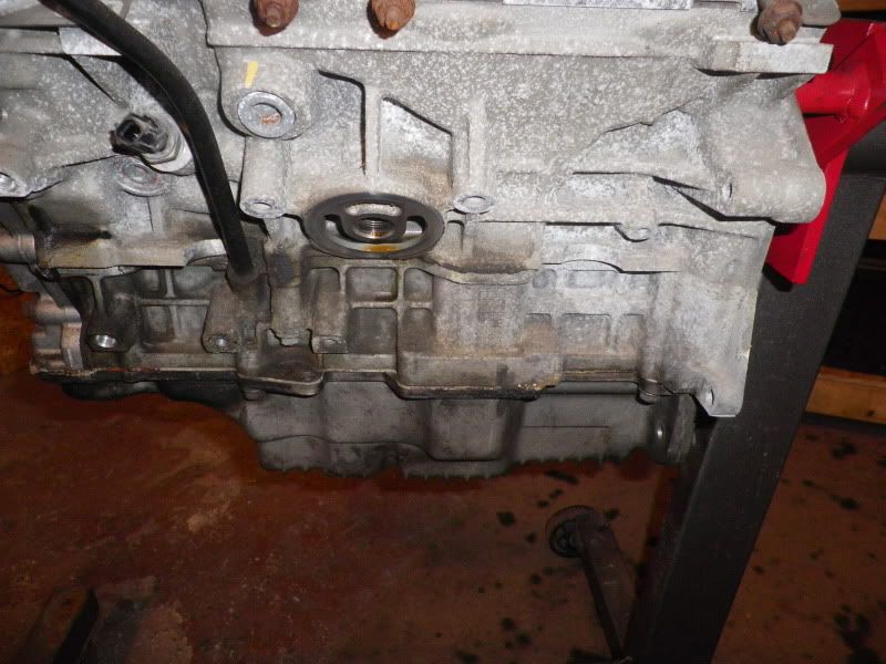
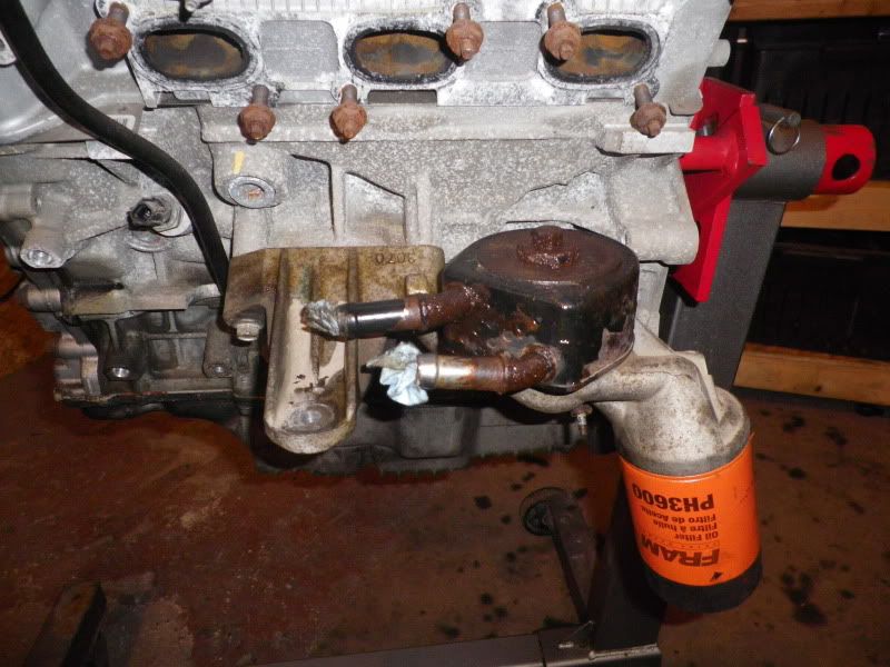
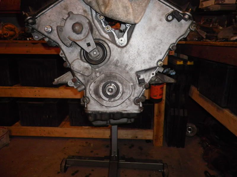
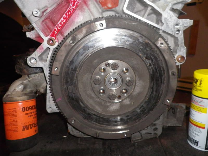
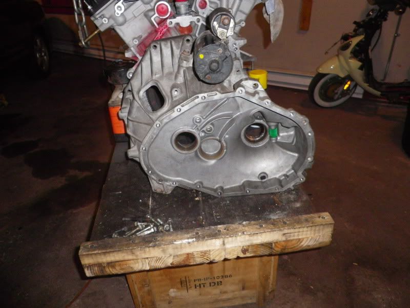
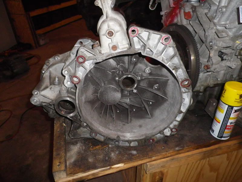
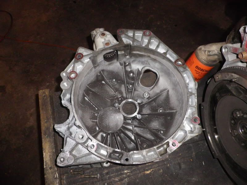
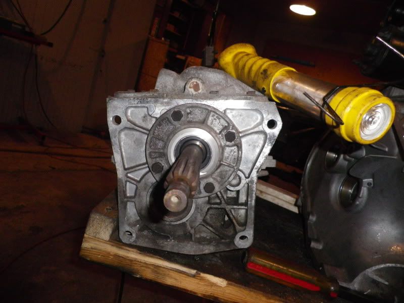
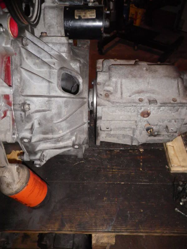
Engine 1 out and engine 2 in:

IMG_0876.jpg


IMG_0999.jpg


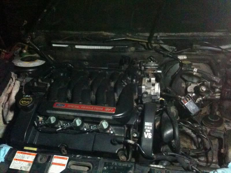
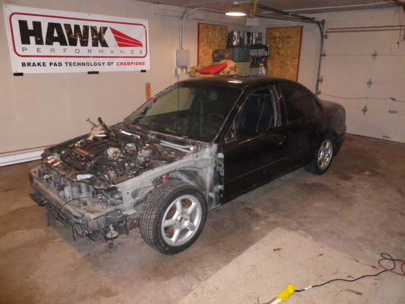
Car as moved to new shop:

IMGP2149.jpg


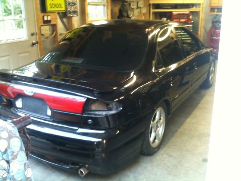
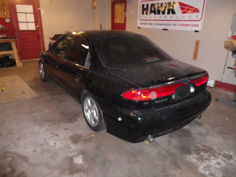
Tail lights installed and trunk swapped for non-wing:

IMGP2150.jpg


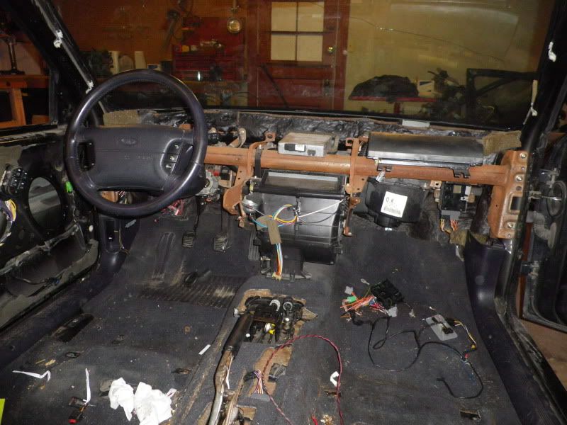
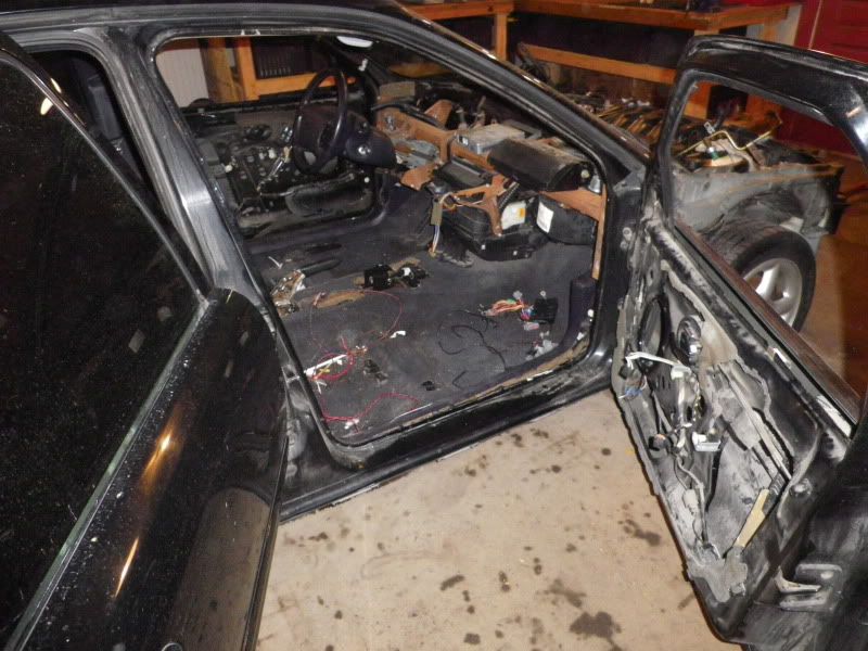
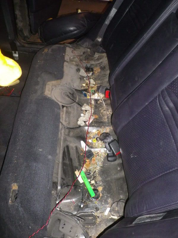
And lastly the interior. There was a lot of work involved in fixing the wiring that was hacked up for things like part removal and an alarm and stereo install at one point, but it has all been repaired and/or replaced thanks to the spare harnesses I have at the shop.

IMGP2164.jpg


IMGP2167.jpg


IMGP2175.jpg
 
I installed front windows and regulators from a parts car before the trans sold and then it was time to pull the motor.

IMGP2194.jpg


Fast forward 2 hours and 10 minutes and she was out.

IMGP2206.jpg


The next order of business was to gut the bay. Much like our track car most of the accessories, emissions control systems and other "clutter" will be removed from the car for a super clean finished product. I started with this:

IMGP2209.jpg


And 3 1/2 hours later was left with:

IMGP2224.jpg


IMGP2230.jpg


IMGP2233.jpg


IMGP2222.jpg


IMGP2235.jpg
 
Now it was time for the fun stuff so we pulled a 3L out of the corner and began assembling our mock-up motor. Now thanks to a lot of research we've found a lot of parts that interchange between Ford's lineup and because the Lincoln LS and Jag S-type came in a RWD format we were able to source locally from a salvage yard the engine mounts. One things to note is that the drivers side mount is rather complex. For the sake of symmetry the mount needed to reside where the engine oil filter typically sits. What they did was built the mount itself into an oil filter relocation and cooler which also gave clearance for where the steering rack needs to pass through. Using this piece simply required removing the filter mount stud from the block. I will also be using the Lincoln LS oil pan, while I was able to take a close up look at an engine assembly and grab some photos of what I need I have yet to source one.


Pass side mount and install:

IMGP2258.jpg


IMGP2259.jpg


Drivers side mount and install:

IMGP2260.jpg


IMGP2261.jpg


IMGP2265.jpg


IMGP2268.jpg


IMGP2272.jpg


IMGP2273.jpg
 
Last update for tonight(I need sleep). I will try to get more written up Tuesday as I have plenty more things documented this far.


At the same time as I picked up the engine mounts I got '00 mustang front knuckles so I took some time to clean them up. More details on this part of things to come later.

IMGP2256.jpg


IMGP2288.jpg


Next up was to get the T-5 trans pilot bearing figured out. Ford did me a favor here. With the torque converter shaft pulled and measurements taken in turned out that a stardard t-5 pilot bearing presses right into the Duratec crank. Getting it out was a breeze.


Factory Torque converter stub in crank:

IMGP2291.jpg


I notched both sides and installed two bolts and simply pried the bushing out with a pry bar working each side a bit at a time. No impact to the crank at all and really quite easy. I will be doing this from now on with all of my 3.0 builds as opposed to just cutting it flush.

IMGP2293.jpg


IMGP2294.jpg


IMGP2296.jpg


IMGP2299.jpg


IMGP2301.jpg


Bearing pressed in and flywheel temp installed for more mock up:

IMGP2302.jpg


That's it for now. Bed time.
 
That's a pretty good idea for pilot bushing removal...I'll remember that when it comes time for me to do that in my 3L swap. Thanks for sharing.
 
I suffered a bit of a set back today as I found that the bell housing model I was using to design the trans adapter is a newer variant and the output bolt pattern is different than the unit I am using. It puts things a few days behind schedule, but at least I caught it early. I did order the clutch today. It is a built to order piece, and should ship in about a week.

Since I left off on pilot bearing yesterday I'll continue on the trans part of things. The intent has always been to retain the duratec bell housing allowing me to use a standard contour flysheel, starter, pressure plate etc and just get a clutch disc with the correct spline and OD. My plan is to make a bolt-on adapter plate that converts the bellhousing to the 94/95 world class t-5 we selected for the build. I selected this trans specifically because for these two years it was produced with a longer input shaft that allows me to use the duratec bell. I am cutting off the un needed portion of the bell as shown in the pictures. There was one modification required to the input bearing housing of the t-5 to allow it to mate fully into the pilot bearing. 1/2 inch of material was removed and with a 1 inch thick adapter plate everything will bolt together very cleanly with proper engagement and clearance throughout. Because this is a mock-up trans I didn't take much car in modifying it to fit. It will look a bit cleaner for the final go-around.


Beginning of bellhousing mod:

IMGP2308.jpg


IMGP2309.jpg


IMGP2311.jpg


Interferance:

IMGP2313.jpg


Solution:

IMGP2321.jpg


IMGP2322.jpg


IMGP2323.jpg


IMGP2330.jpg


All happy:

IMGP2325.jpg


That's it for tonight as I have to be up early to pull the bell before work so I can take measurements at the office and work on fixing the adapter.
 
Whats the plan for the VSS? just guess how fast?

That works off the diff. / output shaft in our transmissions. The t-5 prob has one at the back of it or there will be one mounted in the rear differential (which is where they are typically found on a RWD vehicle)

The VSS is built into the side of the gear box on the T-5. Shouldn't be too difficult to make the car translate it's signal for accurate speeds.
 
Back
Top