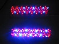
• Welcome to the Contour Enthusiasts Group, the best resource for the Ford Contour and Mercury Mystique.

    You can register to join the community.

door leds

hotdimmes..any chance you have a pic of the "t" thing from when you were doing it. I'm working w/ a set that the slider does not seem to "snap" when it slides both ways. Instead it feels like when it's slide the one way the spring pushes it faster/harder....but when you slide it the other way its kind of like a mushy slide i.e. no "snap"....i think this is what is effecting my rear windows from working right.

Thanks

No pics but that is most likely your problem. I know exactly what you are talking about as I had a ton of problems with it. The best advice I can offer is to set the metal "t" piece down on the switch where it is supposed to go. Then, set the extension of the window lock switch from the cover in the notch in the "t" piece. Bot do so in a manner that it is almost exactly perpendicular to the "t" piece. Then, with both halves of the switch on their sides, push everything back together. This keeps the tab from the window lock switch from moving up or down due to gravity. Hope that helps.
 
well out of the 5 small ones and the master switch only three are done after 4.5 hours. the other two i guess didnt feel as if they needed to work. and yes i switched them over and over again replaced each one a second time and tried it twice again switching and they still didnt work. never even got the chance to do the master switch which im now not looking forward too.ill post up whenever they work
 
make sure you have the right resistors also. Too high of a resistor and they wont work, too low and they will blow (you'll know if they do as they will make a fairly loud POP). Ive even had one shatter:shocked:
 
yeah those two that are black are fried. i have seen some just kind sizzle and turn black, but most of the time they pop. theres a post around here somewhere that tells you how to find what resistor you need.

edit: here it is
and straight to the info page
 
Last edited:
ok that calculator says the original resistors will work for the leds i bought. i noticed that on the calculator picture of the resistor, the resistor has the bronze color band closet to the solder to the LED does that matter? because the two switches that arent working are setup opposite of that picture but only one on the resistors was resoldered on so the other one is still the way the factory had it in there. also does anyone know which way the negative and positive is suppose to go for the inside of the master switch
 
Last edited:
alright well i blew two more today. i gotta order more cause im not gonna have enough to do the master switch cause i bet that will take me about 20 tries to. the two that i couldnt get to work still dont work.ive resodered new bulbs in and i cant think of anything else. if i order new resistors and bulbs is there a special way to get all the solder off so they connect perfectly?
 
alright well i blew two more today. i gotta order more cause im not gonna have enough to do the master switch cause i bet that will take me about 20 tries to. the two that i couldnt get to work still dont work.ive resodered new bulbs in and i cant think of anything else. if i order new resistors and bulbs is there a special way to get all the solder off so they connect perfectly?

Can you tell us where you have the resistor? Is it before or after the incoming voltage (postive to positive leg of LED)? I always put the resistor in after the last LED and before connecting it to the V- (negative wire).

I have been building LED's arrays for a while now, only popped on LED because I intentionally overloaded it to see what would happen.

It's very important you get the voltage reading coming in, do not assume it is exactly 12v. Then use the calculator again to get the correct resistor.

Example, I used 5 red LED at 2.15 V each, so I wire up 5 plus a 68ohm resistor to my 12V source and it works perfect.
 
the resistor is in the same place that the factory ones were because i didnt replace them. i just tried to soder in the new leds. their all located within the window and door switches
 
Did you change the resistor, or use the one that was already in the switch, or a new one?
If you are using the resistor that was there then that may be the culprit. Without knowing what voltage the existing LEDs are, then you run the risk of using the wrong resistor and therefore messing up the amount of voltage running through the LEDs.

And double check the + and -. I had a ***** of time trying to find why my new Mustang LED headlamps were not working properly with the 194A base style LED. After messing around for about an hour I finally found out what side was + and -, fixed that problem.
 

Attachments

  • 10692LEDs_010.jpg
    10692LEDs_010.jpg
    48.3 KB · Views: 0
Last edited:
yea i used the calculator causei know the volts and such for the leds. and ive resodered new leds in each switch twice and netheir one worked and ive also switched it around. i think the problem may be that the solder i got that autozone said works perfect says it is a nonconductive on the back but works with electrics. is there a way to get off the excess solder so its close enough to the current and get some diff solder and resolder it?
 
Back
Top