taken from:
http://www.mirez.co.uk/Trips.htm
(I would reverse any directions of "left" and "Right" orientation, black text = mk1 and mk2, blue = mk1 only, red = mk2 only)
[FONT=Verdana, Arial, Helvetica, sans-serif]
When splicing into wires in the engine bay compartment remember that they are subject to weather conditions. You must either crimp or solder the connections and make sure they are 100% insulated.[/FONT]
[FONT=Verdana, Arial, Helvetica, sans-serif]
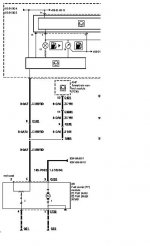
The other two wires go to the large connector just to the left of the passenger side suspension turret. You'll either have 3 small oval connectors here (Early Mk1) or one large square one. In this connector(s) you'll find signals from the VSS (Vehicle Speed Sensor) and from the EEC's fuel flow monitor. It's worth noting that most Mk2 car's have the VSS signal already in the car feeding the speedo and the radio (if speed sence is active). Only Mk1 car's with the auxiliary warning module will have the VSS signal present in the cabin. If you want to find the VSS cable on the back of the radio or behind the instrument cluster (WH/BU) then you can splice it at this point rather then back in the engine bay - you'll still need to connect the fuel flow wire to the engine connector.[/FONT]
[FONT=Verdana, Arial, Helvetica, sans-serif]
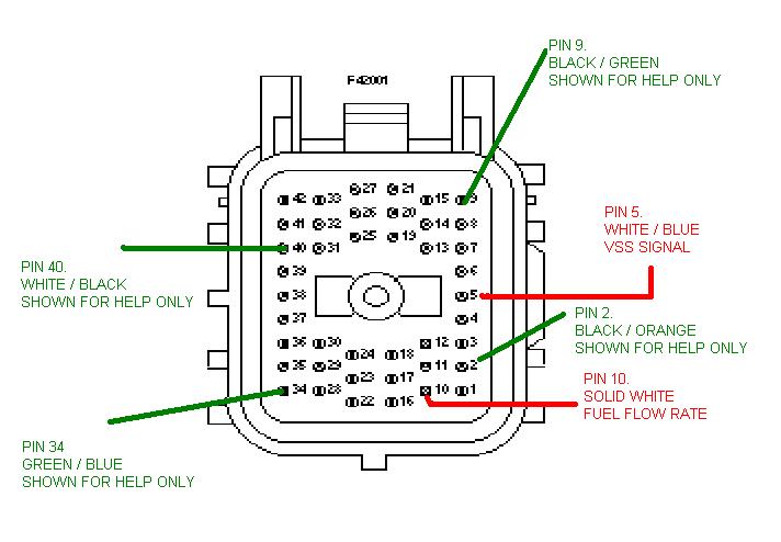
Now this is the trickiest part of the wiring operation as you have to identify the two wires in this connector out of about 40! Whilst is looks like a nightmare, if you take your time and work over the connector methodically you'll find it's actually pretty easy to ID the correct wire. Just remember that there are some colour repeats so take your time and make sure you count the correct number of wires. We'll start with the Mk2 (Note some late Mk1's also use this connector type) Square type connector and the VSS signal. The pin you are looking for in number 5 and is colour coded WHITE/BLUE. This is the easier one to find as the square connector only has 2 WH/BL wires in it. One running through an outter edge pin (the one we want) and the other coming from the centre of the connector. The second we need is a solid white wire running through pin 10 of this connector. Pin 10 is also on an edge and is at the bottom of the row next to the VSS signal.[/FONT]
[FONT=Verdana, Arial, Helvetica, sans-serif]
The colours shown are what SHOULD be at the relevant pins, however Ford have a habit of changing wiring colours for no apparent reason so don't be alarmed if one or possibly two of the help wires are incorrect. Just ensure that PIN5 is WHITE/ BLUE and PIN10 is SOLID WHITE.[/FONT]
[FONT=Verdana, Arial, Helvetica, sans-serif]SQUARE CONNECTOR NOTE: Cars made from Aug 1998 have a different engine loom fitted, as a result the pin locations are different. Pin 28 (Solid White) is the fuel flow wire and Pin 13 (White/VIOLET) is the VSS Signal.[/FONT]


")
 Should see it next week.