• Welcome to the Contour Enthusiasts Group, the best resource for the Ford Contour and Mercury Mystique.

    You can register to join the community.

LED help...

Joined
Jan 13, 2008
Messages
403
Location
Lakewood, WA
Im now thinking of wiring a set of LED tail lights. This will be all home gown so i need to find info.

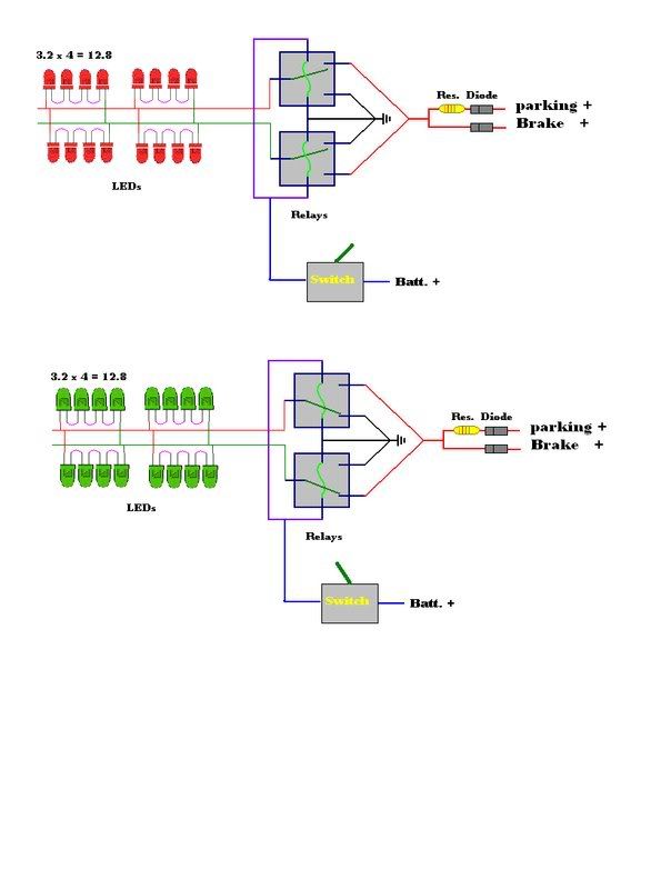
Im Going with 3.4-3.6V Bi-Colored 3 prong LEDs. Green/Red

I know and have the Diodes to block back flow when i bring parking and brake together. I also know what resistor im going to use to drop power down on the parking wire to cause it to be dimmer.... but Im at a lost for the actual set up... this is what i have so far.


If it was a single color i could....
parking+--[diode]--{resistor}--v
Brake+--[Diode]---------------^--(+LED-)---(+LED-)--(+LED-)--(+LED-)-#

With the strand of 4 LEDs (4*3.2) to 12.8 so no Resistors are needed...

But with the 3 lead LEDs i cant chain them together cause what ill need to have will look like this ....
. mmmmmmmmmmmmmmmmmmmGround
Parking--[diode]--{resistor}-vmmm^ -----Red +-----:L D:
Brake----[Diode]------------^-- RELAY ---- Grn +---: E :--- Ground
. mmmmmmmmmmmmmmmmmmmmmv
. mmmmmmmmmmmmmmmmmmmmSwitch

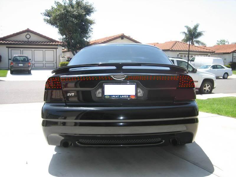
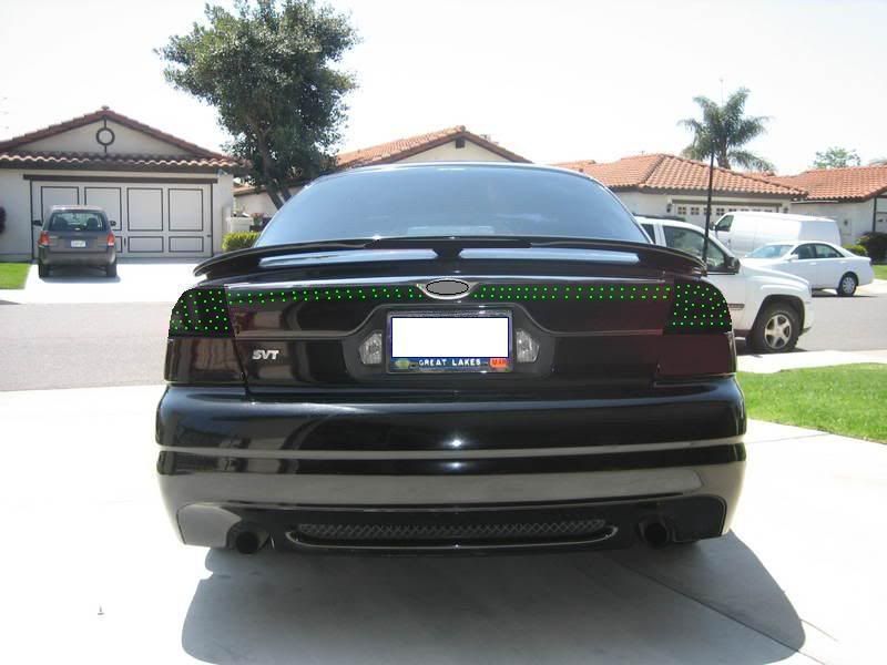
To explain it the parking and brake come together as the imput for the Relay. the relay is switched to put out to the red lead for red brake lights and when the relay is switched it will change the output to Grn Brake lights.
So by having the need change them i cant daisy chain them. All i can think of is just running 3 wires the whole way down.. one R+,R+,R+,R+,R+,R+... and G+,G+,G+,G+,G+,G+... and the ground the same way -,-,-,-,-,-...
but this wont give me resistance like a chain would So any ideas on what resistor i should use?
From what ive found from other ppls math is showing about 320ohms res.
And im still not sure if i should put one on each + lead or maybe just just before the Relay so that res. effects it all or can i put a single res. at the end before the ground???


MAKE ANY SENSE?
if you know electronics it should. Help me out some. lol

Ill post pix when i get started
 
Been over 20 years since I've done any circuit level analog, but unless components have changed a lot, you'd fry the 4 diodes in series with no current limiting resistor (since you mentioned that). What you want is a piece of cake but unfortunately, I don't know for certain exactly what you wnat to do. Have selectable brake light color?

A truth table would be most effective (for me) but since you have already thought it out, google "series connected LED's" (or something like that) and the results should provide the formula for calculating the resistor vale.

Bettre yet, I did the googlee for you!

http://www.kpsec.freeuk.com/components/led.htm
 
Last edited:
The problem with this is, you're going to need a very large amount of LEDs to make it bright enough to be safe; 4 LEDs isn't going to cut it. I've seen guys on here need 70-80 LEDs to make it sufficiently bright. Then you need to put a load simulator in so the car doesn't think a bulb is out. Don't forget that the bulbs in these cars are turn signals and brake lights. You'll also have to modify the tail light to hold an LED strand or board. For the amount of money involved, and the time, it would be a far better idea to leave the stock $1.39 bulb in place.

If you're still dead set on doing it that way, you will need a resistor. The car's current will fluctuate between 12v when partially discharged to ~14v when running. You need to figure your equation with the maximum voltage. Some form of resistor is needed, because the straight current will fry all the LEDs. Also, why would you want to use LEDs that could show up green? They're more expensive I'm guessing... why not just go standard 10mm red or white?
 
Last edited:
disagree on needing a resistor. i have a bunch of led's in series in my gauge cluster (I think 7 or 8 per loop, 2 loops) and I worked it all out so that each gets the appropriate voltage when the car is running. Granted they won't turn on with the car off, but they fade in nicely when starting the car lol. Been running them that way for well over 6 months.

*my post is not applicable if I missed some sort of key electrical information in his post. :)
 
Sorry you i must have missed the point when talking about numbers. Yes more than 4 is needed. I said for casue in a seires that would bring my resistanct to equal the 12v. I then would just run a bunch of these 4 series set ups.

The reason in colors is, well ... y not. I can get a bunch (500) bi colors for 40 bucks. So on a normal the LEDs would be red and when "showing off" they can be green. But with information provided above ... thank you by the way... it seems parallel wouldnt be a wise way to go either. So ill ether have to find my self a volt. regulator to run this system so i can cut it out. or actualy have to put a resistor on each one indiv. because with doing two colors out of a single LED i can not run them in series, there would be no way to change which color lights at that point. ....

Anyone else got any ideas? though i probly will have to go with indiv. Res. ... lol good times... that chart did help with trying to figure out what size res. to use. 12.4 av. on a car 3.4 LEDs... not sure bout the Amps req yet... so still one piece missing. LOL
 
You don't need a volt regular. Just do your calculations with 14v.

Remember that the tail lights are red... green mixed with red isn't going to look the least bit good lol.
 
You don't need a volt regular. Just do your calculations with 14v.

Remember that the tail lights are red... green mixed with red isn't going to look the least bit good lol.

So ur suggesting that i imput 14V for my figure instead of the avg. voltage from the car? that would keep them safe i guess with out really underpowering them... Ok ill work that too...

Btw... the tail lights r blacked out and drilled in pattern with 5mm holes then will be cleared after install. So its not actualy behind the plastic its in it.... i just have to re work reflectors on the rear so i dont get pulled for that.
 
Sounds like an interesting project. Be sure to post pictures during and after the install process.

13.4 is a good average for the car voltage; 14.1 if you want to be safe.
 
When you do your circuit analysis you have to calculate for 'worst case' parameters. Meaning in your case, you have to account for both the highest and the lowest voltages. Your design has to handle the highest possible voltage and it also needs to function as desired at the lowest possible voltage.

With regard to not needing to limit current through the LED's, either the circuit they are in is already limiting current, or these new fangled LED's don't need it. Look at the datasheet!

BTW, since you are playing with colors, the LED's you are using are known as tri-color. If you drive both red and green simultaneously, you'll get yellow. Don't know if you have or have seen equipment that use these, but they are commonly used for indicating OK (green), Warning (yellow), or Fault (red).
 
Last edited:
I think you have it a little off. 3 lead (2 cathode and one anode)Bi color LEDs have just two main colors and ya you can mix them to get a 3rd tone. but when referring to it as a Tri color its actually referring to RGB LEDS that have 4 leads (3 cathode and one anode), that have red green and blue lines in it ... there is also one more way to do a bi color that is only 2 leads. Those who dont know.. its red when you have (+) (-), and green when (-) (+)... meaning rev the flow....

After Doing the math and actualy Plotting it out on graph the best and easiest way to go is im going to go with the bi color 2 lead LED....

Follow me here.... Now i can actually use a series method of 4 to obtain my 12.8v of resistance across the load (5 LEDs @16.1 to be safe) and then of course the resistor of prob. 220 for the parking/braking diff.

that settles that... now we move onto the reversing of the flow...
Who ever has wired up electric locks for their car knows how to set relays up to do this. Of cours usualy its with both relays resting at (-) and one or the other switched to (+) to get the desired effect.. but ill set both relays to the set up to keep red lights one (+) one (-). then when i desire green both relays will move flopping the flow....

Its easy to understand reading it for me being as ive seen the map out ... but for those who cant picture it ill make a pic of it and post...((if i can figure out how to...))

Next is to figure out a design to drill it in... Im thinking two rings following the natural curves of the light with a line in the middle... and thinking about doing two parallel lines across the trunk to kind of bridge them together.and make it function as parking and brake (brake + off the 3rd light so it dosnt flash with blinkers).. .. btw yes im going to do the 3rd brake light to match.. but only in brake not parking...

So if anyone has any other ideas for LED placement design..
 
LED.jpg
 
I think you have it a little off. 3 lead (2 cathode and one anode)Bi color LEDs have just two main colors and ya you can mix them to get a 3rd tone. but when referring to it as a Tri color its actually referring to RGB LEDS that have 4 leads (3 cathode and one anode), that have red green and blue lines in it ...

Well screw me! What will they think of next?!!!! :)

I did do a LITTLE bit of design with relays back in the mid 80's. A schematic of your design would be good .. if anything, draw it out on paper and take a pic if you don't have a scanner. Sounds like you might have the possibility of using a 2 Form C or D relay? (bear with me, that was mid 80's) Anyway, whatever the correct name for it was, it's like a 2PDT switch, and C is a make before break and D is break before make (or vice versa). Since that time, solid state relays have become very 'common place' so you might consider them in case you were think mechanical or reeds.
 
Not at all set up in design ... this is more to give an idea of what it 'should' look like...:laugh:
redtail.jpg

greentail.jpg

Thanks to who evers car this is. It was the best shot i could find of the rear to get a general idea of this on a black CSVT.
 
It's really past my bedtime and I HAVE to get to sleep so I haven't had time to look at your schematic and think much about it, but first thought is .. wait jsut looked at it again and I think that was what I was talking about ...

use a 2 form C or D relay, without looking and thinking about it I'd say it wouldn't matter if it's a make before break or a break before make (but it is a safe call with break before make). Don't know about paralleling the 4 LED assemblies though. I think it used to be that paralleling individual LED's was not the best thing to do ...
 
Nice.... now thats some stuff id like to be able to do... I checked around at some of the other alike videos, omg im not feelin so special now:nonono: LOL i want those now!
 
Well I hope you aren't discouraged to the point you aren't going to continue with your present plans. Just consider it the 'baby steps', the thing you gotta do to get your feet wet. You have to start somewhere!.

If you aren't or haven't been in school in the technologies needed to accomplish what you want, you might consider doing so.
 
Oh for sure... Im too stubborn to stop with my plans.:nonono: But ya i do want to get some books (( cause its only a "hobby") on circuitry. I want to start playin with 555/556 timers for seq. things ... have no clue to it as of now:shrug: but again im hard headed... Ill sit here with it all and a book til i figure it out... So now that i have a general plan for this project, I now need to locate a full set of tail lights to get started:help:... and get the LEDs coming too...Ill post pix as i start and go threw it all...Til then...

:eek:TO BE CONTINUED....
 
The book I highly recommend is "The Art of Electronics" by Paul Horowitz and Winfield Hill. It was recommended to me back in 1989 by a DSP engineer that used to work at SETI with Paul. Unfortunately, it's still at the second edition from 1989 so much of it's contents are outdated (obsolete parts and obviously wouldn't include newer parts and technologies). The book is expensive ($75) and there are expectations for a new Third Edition, so it might be wise to wait awhile. You might also be able to get a used copy off Amazon or something.
 
Last edited:
Back
Top