The only reason AEM says that is because the sensors do go out faster, they dont want a bad name, understandable. Build a heatsink for it if you have problems. The fastest and best reading, next to the turbo, this is pretty widely known. Condensation problems come from positioning, somewhat like what you have. You want the wideband to be at 10 to 2 oclock....

-
Welcome to the Contour Enthusiasts Group, the best resource for the Ford Contour and Mercury Mystique.
You can register to join the community.
You are using an out of date browser. It may not display this or other websites correctly.
You should upgrade or use an alternative browser.
You should upgrade or use an alternative browser.
#49's new powerplant has arrived, let the build begin
- Thread starter CSVT#49
- Start date
CSVT#49
Addicted CEG'er
Condensation problems come from positioning, somewhat like what you have. You want the wideband to be at 10 to 2 oclock....
Yup, I read the instructions from my Innovate LC1 too which states that. That sensor is about at 2-2:30 when looking at it from the front. Any higher and I'd run the risk of hitting the floor board with the sensor lead stressing it at the bend as the exhaust moves up and down. I should be just fine.
elraido
I kant speel
Well, my aug 2nd deadline was shot down.
CSVT#49
Addicted CEG'er
Well, my aug 2nd deadline was shot down.
Oh I didn't tell you? I fired it up last week.
BAD SVT
Addicted CEG'er
Oh I didn't tell you? I fired it up last week.
WhAAAAAAAAAAAAAAAAAAAAAAAAAAAAAAAAAAAAAAAAAAAAAAAAAAAAAAAAAAAAAAAAAAAAAAAAAAAATTTTTT!!! Don't play like that man.
KAOS_3.0
Hard-core CEG'er
I wish we could like posts here....Oh I didn't tell you? I fired it up last week.
rexxdoggy
Hard-core CEG'er
Oh, you lie.
BAD SVT
Addicted CEG'er
Ur silence is deafening mike
CSVT#49
Addicted CEG'er
Really guys? Of course it was a joke... There would be like a 10 min video and a party at my house if it started.
Sent from my ADR6425LVW using Tapatalk
Sent from my ADR6425LVW using Tapatalk
KAOS_3.0
Hard-core CEG'er
we should have a skype drinking contest when this thing is done...
BAD SVT
Addicted CEG'er
Really guys? Of course it was a joke... There would be like a 10 min video and a party at my house if it started.
Oh. Got my heart going for a sec there... The highlight of my year, and i'm sure in speaking for numerous others on here, would be to hear it run. Yes mike, your build is that crucial

TourEnvy
Hard-core CEG'er
Mike, have you reached out to Turbo Hoses in CA for any help in your build? They seemed to be prominent in the Nobel community. Just curious.
CSVT#49
Addicted CEG'er
Mike, have you reached out to Turbo Hoses in CA for any help in your build? They seemed to be prominent in the Nobel community. Just curious.
Yup, I heard Hoover at turbohoses was the guy from TH. I had contacted them years ago before I started this project. However they really didn't provide much help. They are more of a big money outfit, as you mentioned focusing on the Noble community. I learned more from the Noble websites and from some of the other companies out their like Mountune, BPE Racing, Jetstream Motorsports, and many Noble owners. Particularly Greg, who is the owner of the 970hp Noble engine you can find on YouTube...
CSVT#49
Addicted CEG'er
Well I've finally been able to situate the vacuum pump situation. I took apart the adapter that came with the 2011 Chevy Cruise vacuum pump (Hella UP28 pump) to figure out what was going on inside to determine how to wire it. GM apparently took a off the shelf Hella control adapter. They built a micro relay with a capacitor and three diodes onto a board. So I determined the two power pins and ground pin. The one power wire goes straight to the pump and the other goes to the micro relay coil. Third pin is a common ground for the N/O relay circuit and the coil ground. The micro relay is good for 15A and the vacuum pump has a peak of 15A draw, but the adjustable vacuum switch that I have is only rated for 10A. So I'll be wiring the vacuum switch as a switched power to the coil of the relay.
The other hold up was the mysterious connector on the end of the Hella adapter. It looked familiar to me, but I couldn't quite place it. After searching the web for a while I found it and then I realized why it looked familiar. Apparently Hella decided to use the Bosch LSU 4.2 wide band connector for their adapter. Thanks to VEMS I found the mating connector for $8.50. Once I receive the connector the last piece of the puzzle should be complete!
The other hold up was the mysterious connector on the end of the Hella adapter. It looked familiar to me, but I couldn't quite place it. After searching the web for a while I found it and then I realized why it looked familiar. Apparently Hella decided to use the Bosch LSU 4.2 wide band connector for their adapter. Thanks to VEMS I found the mating connector for $8.50. Once I receive the connector the last piece of the puzzle should be complete!
crewchiefpro
Hard-core CEG'er
I am curious if you can pull real vacuum out of the engine with this setup. I know it will work on a power brake booster, just not sure it will pull enough vacuum in a large motor. I guess you will see after you apply power to it and check. Do you have a vacuum gauge? I think you could take an old oil fill cap and drill a hole to put the vacuum gauge in and test it.
CSVT#49
Addicted CEG'er
I am curious if you can pull real vacuum out of the engine with this setup. I know it will work on a power brake booster, just not sure it will pull enough vacuum in a large motor. I guess you will see after you apply power to it and check. Do you have a vacuum gauge? I think you could take an old oil fill cap and drill a hole to put the vacuum gauge in and test it.
The vacuum pump isn't intended to pull a vacuum on the entire engine. It is only there to provide assistance in maintaining vacuum. However that said if I wanted to I could use a Hella UP32 vacuum pump to do just that.
crewchiefpro
Hard-core CEG'er
The vacuum pump isn't intended to pull a vacuum on the entire engine. It is only there to provide assistance in maintaining vacuum. However that said if I wanted to I could use a Hella UP32 vacuum pump to do just that.
? Not understanding the phrase "maintaining vacuum". There is no vacuum in the crankcase, only pressure from the pistons going up and down, plus some blow by from the rings. I use a vacuum pump to remove pressure and add vacuum so there will be more HP and no oil leaks. In order to function as such it will require at least 10" of vacuum while the engine is running.
I guess I don't understand what your goals are with this setup.
EDIT: Are you just using this for the braking system?
CSVT#49
Addicted CEG'er
EDIT: Are you just using this for the braking system?
Yes. It will be doing exactly as your describing and to ensure vacuum is there for the brakes. The maintaining vacuum comment was directed towards the brakes.
The system will consist of a vacuum pump and an adjustable vacuum switch. The vacuum pump will be plumbed into the line feeding the brake booster, but by doing so will also be plumbed into the PVC system as well. The vacuum switch will be plumbed ahead of the tee monitoring the vacuum at the brake booster. Once the vacuum drops below (I'm thinking 13") I will have the vacuum pump kick on. The vacuum pump will exhaust the pulled air ahead of the turbo, but after the MAF.
CSVT#49
Addicted CEG'er
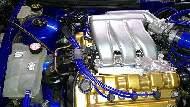
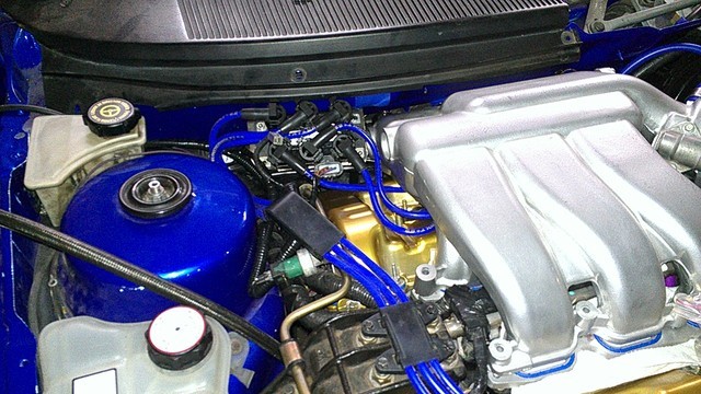
Coil pack is mounted. I used the studs off the fire wall for the insulation. Because of this I also ran a ground strap from the bracket to the engine. Worked out quite well. The #3 wire is a bit of a stretch, but I feel there is enough slack for engine movement.
Finishing up a bracket to install the oil catch can. This should allow me to finish all of the vacuum line routing and bolt the UIM down. After that I need to take apart the front hubs to install the DSS hubs and axles... after which install the battery, flash the ECM, and fire it up!
Finishing up a bracket to install the oil catch can. This should allow me to finish all of the vacuum line routing and bolt the UIM down. After that I need to take apart the front hubs to install the DSS hubs and axles... after which install the battery, flash the ECM, and fire it up!
codireinert
CEG'er
So does it run and everything now??