|
|
Joined: Sep 2002
Posts: 3,944
Hard-core CEG'er
|
OP

Hard-core CEG'er
Joined: Sep 2002
Posts: 3,944 |
A very special thanks to SHOTIME2669 for this How-To!!
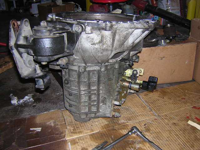
Ok this how-to will not describe how to remove the transaxle from your car or install it, but rather just how to take it apart and upgrade the components. I will be installing the shift forks, shift tower and a Torsen differential. With that said lets continueâ�?�¦
Set yourself up for the job. You will need a large amount of work space to allow for the transaxle disassembly. Here are the list of tools I used and then a list of Ford recommended tools along with a list of the parts and supplies needed.
Tools:
13mm, 10mm, and 8mm sockets
13mm open end wrench
7/8�� open end wrench
Breaker bar
3/8�� drive ratchet
3/8�� drive extension
1/2�� drive ratchet
1/2�� drive extension
Large gear puller
Torque wrench
Flat head screw driver
2 Blocks of wood
3 Plastic bags zip lock bags
Pry bar
Ford recommended tools:
Puller (T58L-101-B)
Impact Slide Hammer (T50T-100-A)
Stator and Driven Sprocket Remover (T86P-70043-A)
Driver Handle (T80T-4000-W)
Transfer Case Output Seal Replacer (T87P-7065-B)
Differential Bearing Cone Replacer (T94P7025GH)
Ford Parts:
YS2Z-7230-BA Fork-Gea
YS4Z-7230-AD Fork 3rd
XS8Z-7240-DD Fork-Gea
XS4Z-7201-CD Focus Shift Tower
YS4Z-15525-BA Reverse light switch adapter harness
YS4Z-15520-BA Reverse light switch
XS4Z-7L282-AA Vent
YS4Z-7222-AC Shift tower cover
YS4Z-7412-JA Shift tower clamp 1
YS4Z-7412-HA Shift tower clamp 2
F7RZ-4221-AC Differential bearing (need 2)
F5RZ-17285-AA Speedo gear for VSS
XL-3 Ford additive friction modifier
M-4204-F20 Torsen T2 differential
Non-Ford Parts/supplies:
242 Loctite or equivalent
Permatex Ultra Black Hi-Temp RTV silicone Part# 598B
Junk yard marker or paint pen
6 M8-16 bolts
6 M8 flat washers
6 M8 lock washers
Notes prior to disassembly:
The above tools can be rented from auto parts stores like Checker/CSK auto if you don���?�t have them.
Before beginning the install make sure you have the bearings and speedo gear pressed onto the Torsen differential by a transmission shop. Unless of course you have the means of doing it yourself
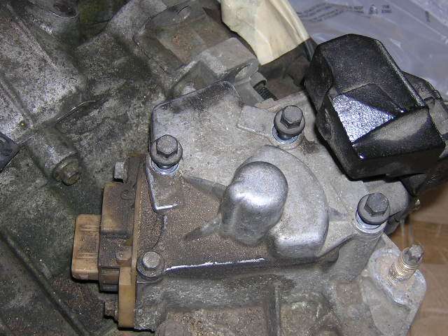
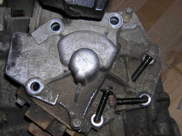
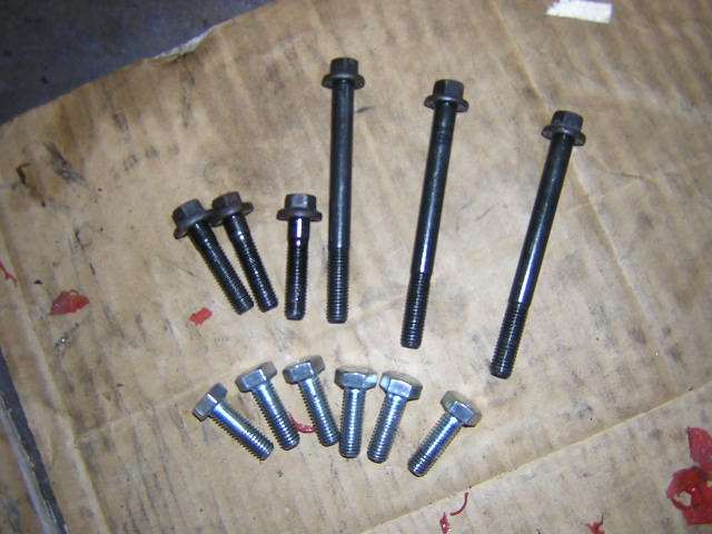
1) Remove the shift tower from the case. There are 6 bolts that require the 10mm socket for removal. There will be 3 long bolts and 3 short bolts. Place these bolts in a zip lock bag and label accordingly.
2) Once the shift tower has been removed loosen and remove the bolts around the bell housing. There will be a total of 16 bolts and 2 studs the bolts will be 10mm and the two studs will be 17mm. Note the holes to which the studs go to with a junk yard marker or paint. Place the bolts and studs in a zip lock bag and label accordingly.
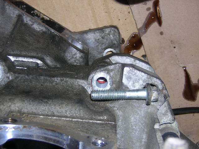
3) Place the transaxle up right with the bell housing facing up. With the bell housing bolts removed use the pry bar to loose the bell housing from the case and then remove it. Be very careful not to crack the case.
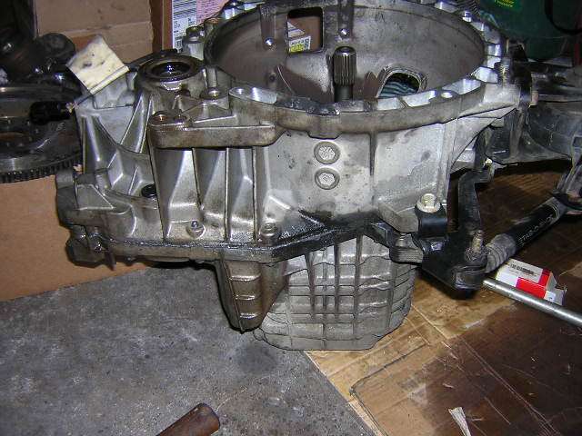
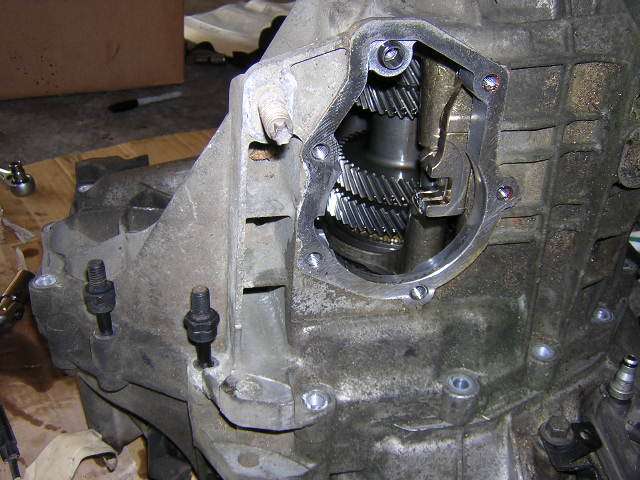
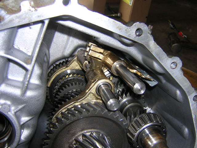
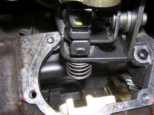
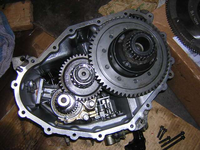
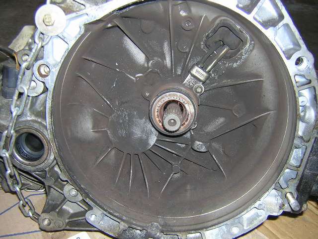
4) Once the bell housing is removed from the case you will now have exposed the differential and the rest of the internals (input shaft, output shaft, shift forks, etc.)
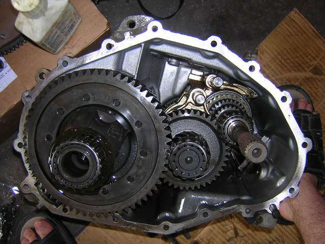
5) Remove the differential from the case and set aside.
6) Remove the selector rods (rods that are holding shift forks in place)
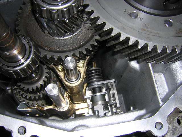
7) Remove the shift forks one by noting where each one goes. Match them up with the new parts and reinstall. They slide out very easily and go in the same way.
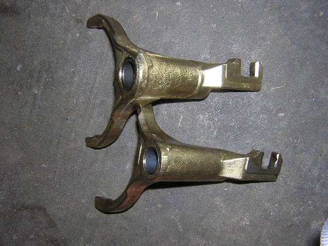
You can see the difference in the forks
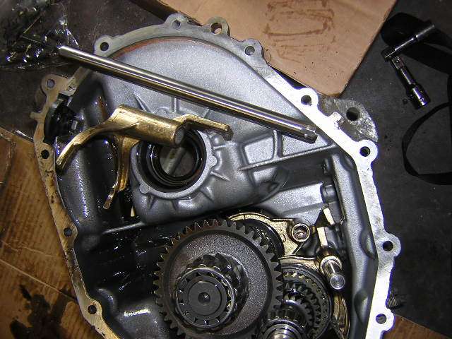
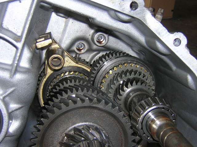
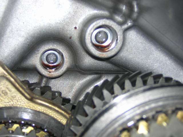
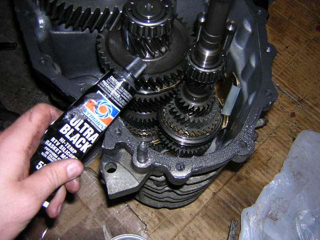
8) With the new shift forks installed reinstall the selector rods. Be sure they set in the placement holes at the bottom of the case (pictured below). You know you have installed them right if they are both sitting at the same height.
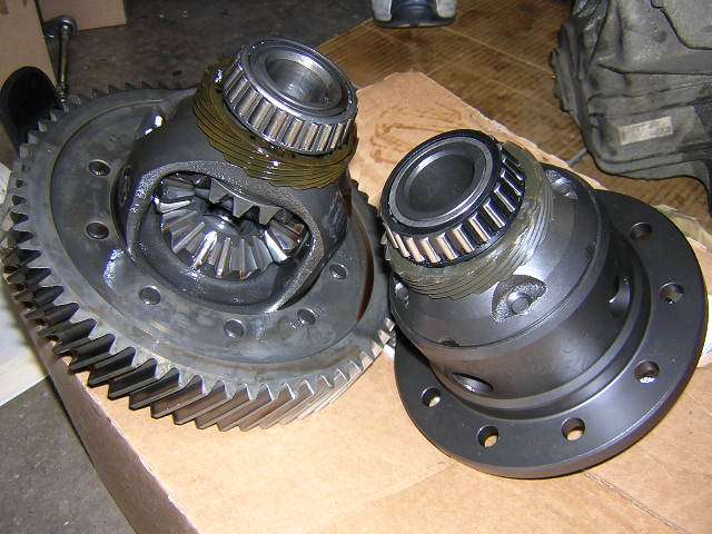
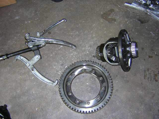
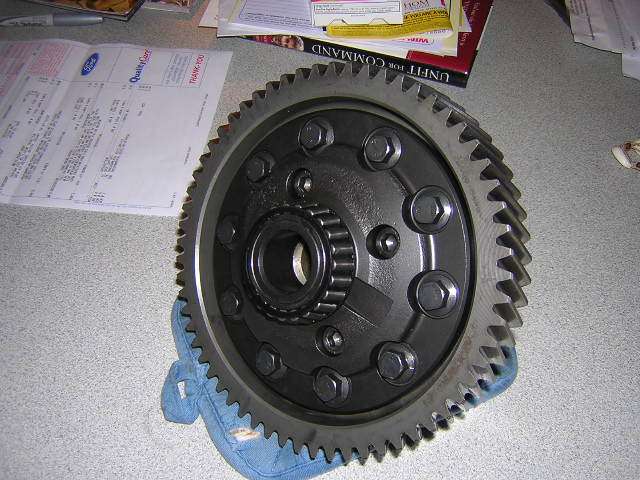
9) Now turn your attention to the differential. The ring gear must be removed from the old diff to reinstall the Torsen T2 diff. Using a breaker bar with a 13mm socket and a ratchet with a 13mm socket/or 13mm open end wrench hold one bolt on the differential and break another bolt loose. Make your way around the diff until all bolts are loose. On the last bolt you will need to hold the differential with a towel and loosen the bolt with the breaker bar. This may take two people, but I was able to do it by myself. Place the bolts in a zip lock bag and label accordingly for later use.
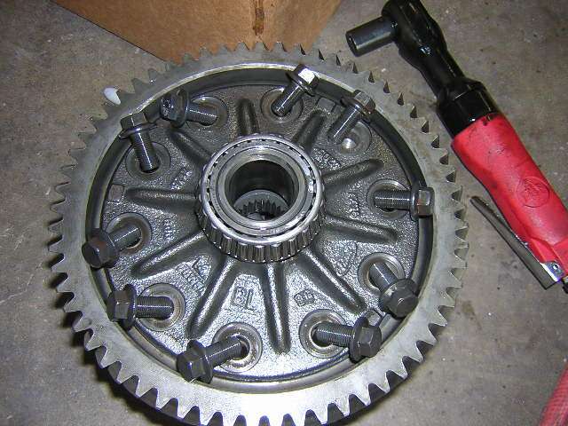
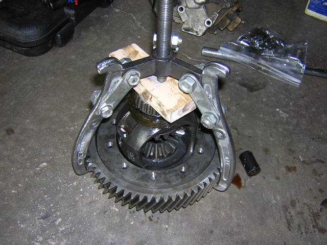
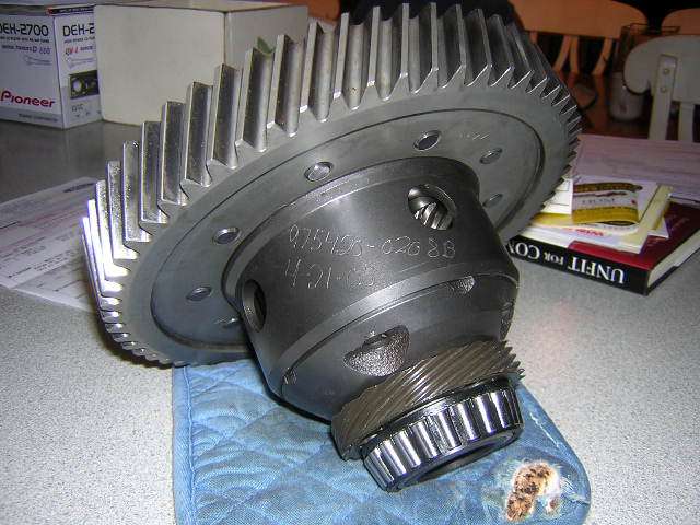
10) With all of the bolts removed from the ring gear place a block over the end of the differential and use the large gear puller to remove the ring gear from the differential as shown.
11) Once the ring gear has been removed place the new Torsen differential in the freezer and the ring gear in the oven set at 350�?°F and let both sit for approximately 15-20min.
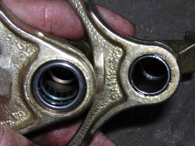
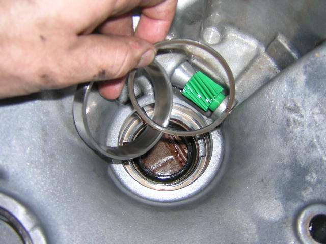
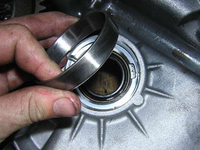
12) While the ring gear is heating and the Torsen diff is cooling go back to the case and remove the races from the old diff���?�s bearings. This is where having the Ford tools listed at the beginning comes in handy. If you have the tools use the stator and driven sprocket remove with the puller to remove the races. I didn���?�t have this tool and didn���?�t realize I could rent it at the time so I used two flat head screw drives to pry them up and out. I don���?�t recommend doing it this way, but if you do be sure not to scratch up the mating surfaces. Once the races are removed be sure to keep any shims that were in place and note were they go ( you may want to place them in a zip lock bag and label them accordingly)
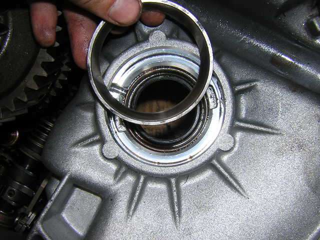
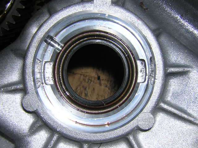
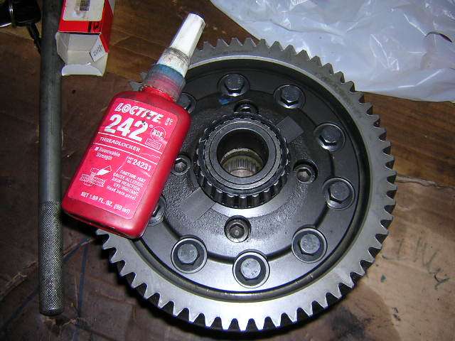
With the race removed this is what you will see, notice the notches where the stator tool would fit.
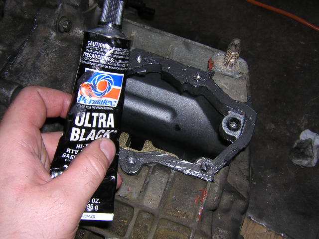
13) Obtain the bag with the ring gear bolts as well as an open end wrench to start them in with. Retrieve the Torsen diff from the freezer (as you do this place the new bearing races in the freezer) and set it up right so it is ready to receive the hot ring gear. Grab the ring gear from the oven with some hot mitts and place it on the differential. You should not have to force it on. If you do replace the ring gear back in the oven and the diff back in the freezer and try again later. If it slides on without any problems line it up with the bolt holes are start the bolts (you may want to use the 242 loctite on the bolts) tighten the bolts with the open end wrench and allow the differential to cool.
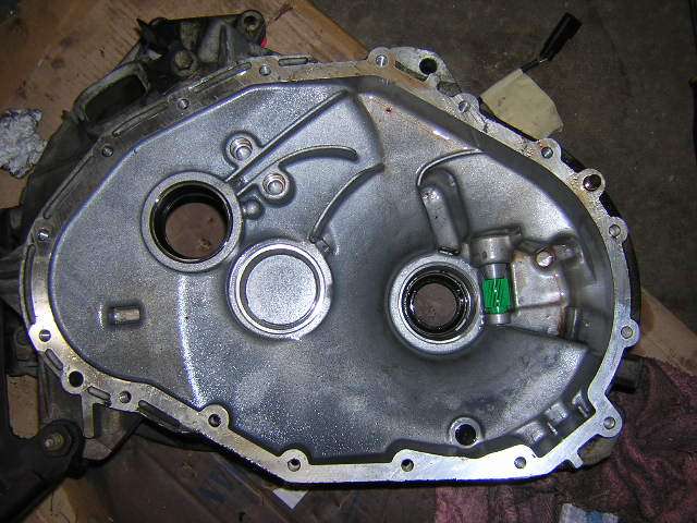
14) While the differential is cooling install the new shift tower. Before installing the shift tower ensure that both the shift forks and the shift tower are all aligned and that they are in the neutral position (shown below) Clean the mounting surface (I used brake a can of brake cleaner and some paper towel) of the shift tower and then apply a sealant (Permatex ultra black RTV) to the surface and bottom of shift tower. Place the shift tower in place and bolt it on using the 6 M8-16 bolts with a flat washer and a lock washer on each. Torque the bolts to 32Nm doing so in a diagonal pattern. Then screw in the new reverse light switch accordingly, it���?�ll take a 7/8�� wrench.
NOTE: Bolts should be tightened within half an hour of applying sealant

15) After the shift tower has been installed go and retrieve the new races for the differential bearings in the freezer. Place the shims that you removed from the previous races in their corresponding spots (Ford states that there should be one 10mm shim for the differential, I found this shim on the bell housing side next to the VSS gear) The new races should fall right into place since they have been cooled. However if they do not, this again is where having the Ford recommend tools comes in handy again. Using Driver Handle (T80T-4000-W), Transfer Case Output Seal Replacer (T87P-7065-B), and Differential Bearing Cone Replacer (T94P7025GH) you should be able to replace the races. I replaced the races back in the freezer until they dropped into place.
16) With the new races installed take the now cooled differential/ring gear assembly and torque the bolts to 88Nm in a diagonal pattern. I did this by putting a set of wooden blocks in a vise with the ring gear sandwiched between them.
17) Put the differential in place making sure the ring gear is mating correctly with the output shaft gear and that the bearing is sitting correctly in the newly installed race.
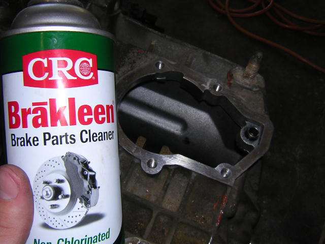
18) Clean the surface of the case and the bell housing (again I used brake cleaner and paper towel) and apply sealant (Permatex ultra black RTV #598B). Place the bell housing over the case ensuring that the pins are aligned and push it into place. You may need to use a rubber mallet to get it to sit all the way down.
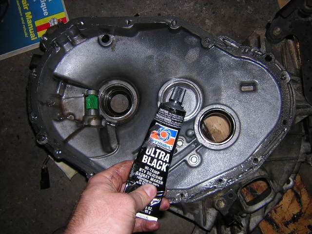
19) With the transaxle still sitting up right with the bell housing facing up; install the bell housing 10mm bolts into place along with the 17mm studs (ensure that these studs get placed in the right holes that where marked with the marker or paint earlier) Torque all these bolts and studs to 32Nm.
NOTE: Bolts should be tightened within half an hour of applying sealant
20) Now that the case is assembled replace the slave cylinder/throw-out bearing assembly. The assembly is located in the bell housing over the input shaft. It���?�s held into place by 3 bolts. Using an 8mm socket remove the bolts and take off the rubber dust cover that is over the lines.
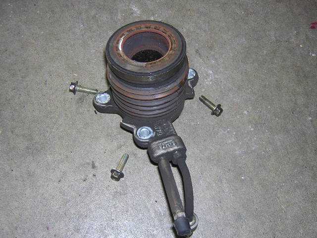
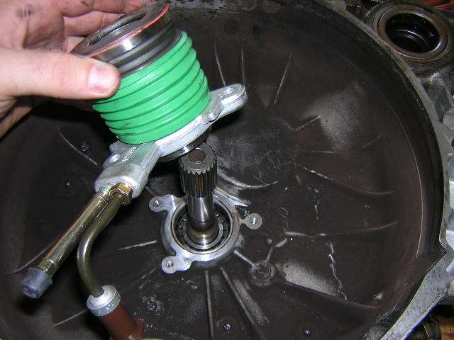
21) Clean the surface and install the new slave cylinder. Torque the bolts to 10Nm and install the new dust cover over the lines.
Make sure the boot fitment is correct around the edges.
Notes after assembly:
Make sure upon filling the transaxle with gear oil you include the additive friction modifier from Ford. I also suggest using Red line MTL 75W80 oil I���?�ve heard only good things about the stuff.
Congratulations. You have just successfully upgraded your factory MTX-75 transaxle.
Special thanks to:
-Master Transmission of Rosemount, MN who installed my differential bearings free of charge.
-Steve and Mike at Tousley Ford, White Bear Lake, MN who helped me get the parts I needed and saved my some serious coin. 1-800-328-9552 ask for Steve or Mike
-Chris (Blackcoog) for helping me out with getting the right list of parts and answering my questions.
-Digital Slacker for initially hosting the pictures
Last edited by unisys12; 08/10/05 02:57 AM.
Phillip Jackson
`98 Mystique LS
262K+ and counting...
ATX rebuilt @ 151K
"This storm has broken me, my only friend!" RIP Dime
|
|
|
|
|
Joined: May 2004
Posts: 636
Veteran CEG\'er
|
|
Veteran CEG\'er
Joined: May 2004
Posts: 636 |
Despite some minor problems with getting the ring gear on and having to replace my VSS it all went pretty smooth. I hope this how-to is clear enough and provides all the necessary information about how to get the job done.
 Enjoy everyone!
Thanks for taking care of the post unisys12 and inserting those spaces.
Also if anyone has questions or needs more pictures providing a little more detail on some of the steps in this how-to just drop me a PM or email and I'll hook you up. I left out about half the pictures just because I didn't want this post to be 3 pages long.
-Mike
98 Contour SVT
Toreador Red #49 of 6535 Built on 3/25/97
WR Headers, Borla Cat-Back, Torsen T2 LSD, K&N Short Ram, S-AFC and Focus Shift Tower
85 Camaro
1969 358ci, 97 TA interior, 91 Z28 GrdEfx and Aero Wing 255rwhp
|
|
|
|
|
Joined: May 2004
Posts: 636
Veteran CEG\'er
|
|
Veteran CEG\'er
Joined: May 2004
Posts: 636 |
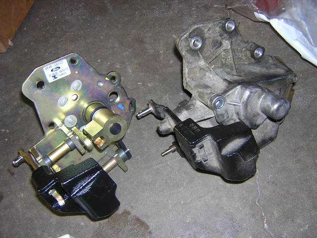
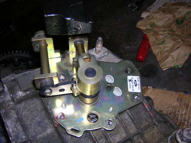
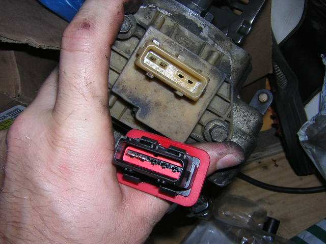
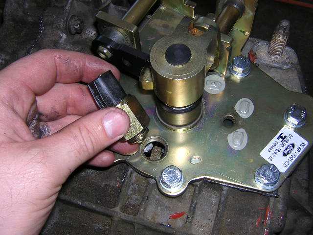
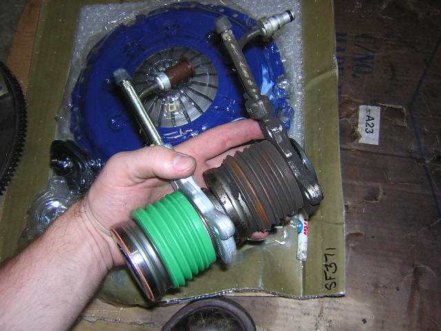
I also just realized that this how-to didn't touch on the linkages. I have not yet installed this transaxle in my car so I have no installation pictures. However here are pictures of the parts you should have in your possession when you are finished here. 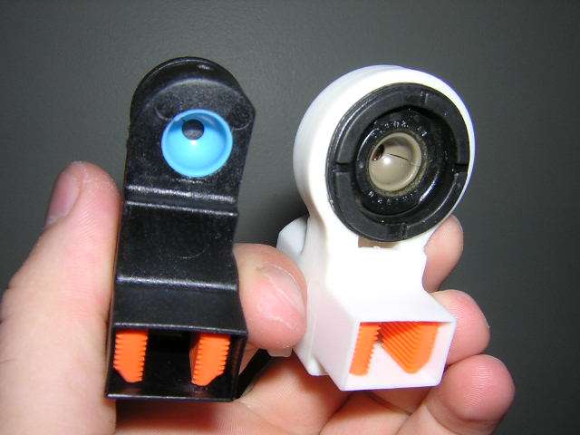 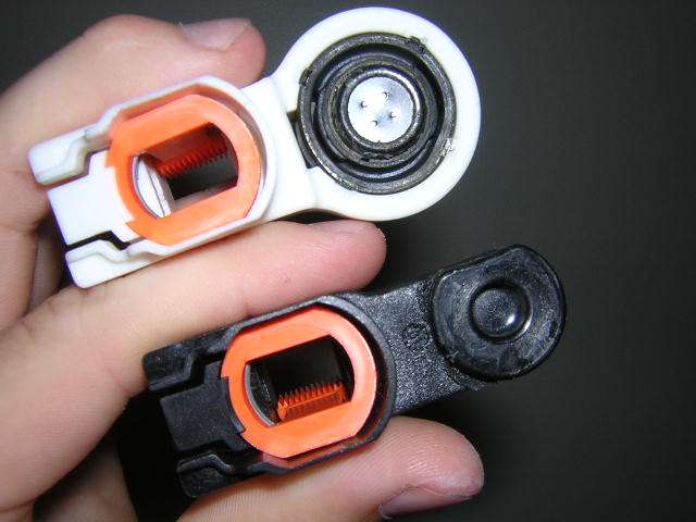 I'll add more pictures after I get the transaxle and the engine back in my car. That way you can see the connections.
-Mike
98 Contour SVT
Toreador Red #49 of 6535 Built on 3/25/97
WR Headers, Borla Cat-Back, Torsen T2 LSD, K&N Short Ram, S-AFC and Focus Shift Tower
85 Camaro
1969 358ci, 97 TA interior, 91 Z28 GrdEfx and Aero Wing 255rwhp
|
|
|
|
|
Joined: Nov 2000
Posts: 611
Veteran CEG\'er
|
|
Veteran CEG\'er
Joined: Nov 2000
Posts: 611 |
There are ears on the transmission for prying it apart. You do not want to pry it apart with a crow bar or screw driver in any other place but where those points are. If you jam a screw driver or crow bar between the cases you will scratch up the mating surfaces and your transmission will leak even if you put RTV sealant on it when putting it back together. I've seen it happen before. Just an FYI for all you reading the how-to.
1999 3.0L Cougar: 220fwhp and 200tq
2003 VW Passat W8 with 4 Motion AWD
http://www.cardomain.com/ride/300644
PM for intrest in 3L SVT Contours, 3L swaps into your current car, Prepped 3L engines, or anything 3L related.
|
|
|
|
|
Joined: Mar 2004
Posts: 4,141
Hard-core CEG\'er
|
|
Hard-core CEG\'er
Joined: Mar 2004
Posts: 4,141 |
amazing how to.....mad props to you man.
i can't waite to dive into my trans now.
99 SE V6\5spd - 156 HP\157 TQ 15.166-90.84
Totaled 02/12/06
99 SVT # 1571 - 175 HP\153 TQ 14.999-91.88
Born 3/24/99 Reborn 3/18/06
Pietenpol Racing Technologies project vehicle
90 Festiva L 5spd, Blue(not for long), 103k
|
|
|
|
|
Joined: May 2004
Posts: 636
Veteran CEG\'er
|
|
Veteran CEG\'er
Joined: May 2004
Posts: 636 |
Good call Chris. I forgot to mention that.
The ears can be seen in the 4th, 6th and 7th pictures in the how-to. There is one on each side.
-Mike
98 Contour SVT
Toreador Red #49 of 6535 Built on 3/25/97
WR Headers, Borla Cat-Back, Torsen T2 LSD, K&N Short Ram, S-AFC and Focus Shift Tower
85 Camaro
1969 358ci, 97 TA interior, 91 Z28 GrdEfx and Aero Wing 255rwhp
|
|
|
|
|
Joined: Feb 2005
Posts: 1,572
Hard-core CEG\'er
|
|
Hard-core CEG\'er
Joined: Feb 2005
Posts: 1,572 |
Originally posted by pole120:
amazing how to.....mad props to you man.
i can't waite to dive into my trans now.
I can't belive how easy that really look's . I read the page over and over to make sure I knew exactly what was going on and I know I can do this . I asked a local guy at a trans shop about doing them for me a while back and he pretty much ran away from me with FEAR ....he plain said NO WAY its a nightmare ..
From what I can see less then 20 bolts , pry it apart , pull out the 2 shafts and change out the forks , and reassemble ...
Thanks for all this help !!! Nice to have this info ..
Check me out for awsome powder coating deals
www.powdercoatingworld.com
People shouldn't slam each other when posting, If you cant say something good to say then just hit the back arrow.
|
|
|
|
|
Joined: Feb 2005
Posts: 1,572
Hard-core CEG\'er
|
|
Hard-core CEG\'er
Joined: Feb 2005
Posts: 1,572 |
Sorry but do you have part numbers for the linkage shown ?
Check me out for awsome powder coating deals
www.powdercoatingworld.com
People shouldn't slam each other when posting, If you cant say something good to say then just hit the back arrow.
|
|
|
|
|
Joined: May 2004
Posts: 636
Veteran CEG\'er
|
|
Veteran CEG\'er
Joined: May 2004
Posts: 636 |
The part numbers for the linkages are at the top of the How-To, in the list of Ford Parts.
YS4Z-7412-JA Shift tower clamp 1
YS4Z-7412-HA Shift tower clamp 2
I realize they say clamp, but the were referred to that in an earlier post from someone else. So I stuck with it to avoid complications.
You don't even have to pull the shafts out. You just have to move them to the side a bit and slide the forks on.
The process is easy you just need to have the tools to do it.
-Mike
98 Contour SVT
Toreador Red #49 of 6535 Built on 3/25/97
WR Headers, Borla Cat-Back, Torsen T2 LSD, K&N Short Ram, S-AFC and Focus Shift Tower
85 Camaro
1969 358ci, 97 TA interior, 91 Z28 GrdEfx and Aero Wing 255rwhp
|
|
|
|
|
Joined: Feb 2005
Posts: 1,572
Hard-core CEG\'er
|
|
Hard-core CEG\'er
Joined: Feb 2005
Posts: 1,572 |
Check me out for awsome powder coating deals
www.powdercoatingworld.com
People shouldn't slam each other when posting, If you cant say something good to say then just hit the back arrow.
|
|
|
|
|
Joined: Mar 2004
Posts: 4,141
Hard-core CEG\'er
|
|
Hard-core CEG\'er
Joined: Mar 2004
Posts: 4,141 |
99 SE V6\5spd - 156 HP\157 TQ 15.166-90.84
Totaled 02/12/06
99 SVT # 1571 - 175 HP\153 TQ 14.999-91.88
Born 3/24/99 Reborn 3/18/06
Pietenpol Racing Technologies project vehicle
90 Festiva L 5spd, Blue(not for long), 103k
|
|
|
|
|
Joined: Feb 2005
Posts: 1,572
Hard-core CEG\'er
|
|
Hard-core CEG\'er
Joined: Feb 2005
Posts: 1,572 |
Thats odd I jsut looked all over my CD and I can't even find the MTX-75 listed . I have
AX4N
AX4S
F4EIII
F4E TYPE F
CD4E
CD4E is the one listed for the Contour / Cougar / Mystique
Check me out for awsome powder coating deals
www.powdercoatingworld.com
People shouldn't slam each other when posting, If you cant say something good to say then just hit the back arrow.
|
|
|
|
|
Joined: May 2004
Posts: 636
Veteran CEG\'er
|
|
Veteran CEG\'er
Joined: May 2004
Posts: 636 |
Any chance of getting that removal instruction post deleted? That way we can avoid confusing people. Grant it there may be some useful info there... but yea wrong trans.
-Mike
-Mike
98 Contour SVT
Toreador Red #49 of 6535 Built on 3/25/97
WR Headers, Borla Cat-Back, Torsen T2 LSD, K&N Short Ram, S-AFC and Focus Shift Tower
85 Camaro
1969 358ci, 97 TA interior, 91 Z28 GrdEfx and Aero Wing 255rwhp
|
|
|
|
|
Joined: Feb 2005
Posts: 1,572
Hard-core CEG\'er
|
|
Hard-core CEG\'er
Joined: Feb 2005
Posts: 1,572 |
Originally posted by SHOTIME2669:
Any chance of getting that removal instruction post deleted? That way we can avoid confusing people.
-Mike
I just tried to edit it and remove it , I was actually trying to help out but I guess that didn't work as planned , A mod will remove it I'm sure.
Check me out for awsome powder coating deals
www.powdercoatingworld.com
People shouldn't slam each other when posting, If you cant say something good to say then just hit the back arrow.
|
|
|
|
|
Joined: May 2004
Posts: 636
Veteran CEG\'er
|
|
Veteran CEG\'er
Joined: May 2004
Posts: 636 |
I know you were trying to help. Thanks for trying, so since there seems to be a demand... Heres the correct way:
Special Tools Needed (According to Ford)
Support Bar, Engine 21 - 140
Adapter for 21-140, 21 - 140 - 01
Adapter for 21-140, 21 - 140 - 02
Adapter for 21-140, 21 - 140 - 03
Hi - Lift Transmission Jack 014 - 000942
Powertrain Fixture 134 - 000250 (optional)
Impact Slide Hammer, T50T-100-A
Metric Hub Remover Adapters, T83P-1104-BH
CV Joint Puller, T86P-3514-A
Removal
1.Remove the battery. For additional information, refer to �?«Section 414-01�?».
2.On both sides undo the suspension strut nut five turns.
3 CAUTION:
Lock the steering wheel.
Use wire or tie strap to secure the radiator.
4.Remove the engine air cleaner (A/C). For additional information, refer to �?«Section 303-12B�?».
5.Remove the water pump cover.
(1) Disconnect the engine coolant hose.
(2) Remove the bolts.
(3) Remove the water pump cover.
6. Disconnect the accelerator and speed control cables.
(1) Disconnect the speed control cable, if equipped.
(2) Disconnect the throttle cable.
7. Disconnect the accelerator and speed control cables (SVT Vehicles only).
(1) Unclip the cables from the bracket.
(2) Disconnect the accelerator and speed control cables.
8. Disconnect the ground cable and position it aside.
9. Note:
Drain the power steering reservoir.
Disconnect the power steering reservoir hose.
(1) Disconnect the power steering reservoir from the bracket by lifting up.
(2) Reposition the hose clamp.
(3) Disconnect the power steering reservoir hose.
10. Disconnect the vehicle speed sensor (VSS) electrical connector and reversing lamp switch electrical connector.
11. Disconnect the fuel lines. For additional information, refer to �?«Section 310-00�?».
12. Disconnect the starter motor electrical connectors.
13. Remove the air cleaner bracket and the starter motor bracket.
(1) Remove the air cleaner bracket.
(2) Remove the starter motor bracket.
14.CAUTION:
Do not spill brake fluid onto painted surfaces.
Remove the clutch slave cylinder hydraulic pipe.
15. Remove the bolts and the starter motor.
Refer to corresponding illustration.
16. Install the Support Bar, Engine.
17. Remove the LH transaxle support insulator.
(1) Remove the nuts.
(2) Remove the bolts.
(3) Remove the LH transaxle support insulator.
18. Remove the LH transaxle support insulator studs.
19. Remove the four upper bellhousing bolts.
20. Remove the front wheels.
21. Detach the lower wheel arch covers (right-hand side shown).
22.CAUTION:
Do not damage boot and ABS - Sensor Ring.
Disconnect the lower suspension arm ball joints and the stabilizer link rods (right - hand side shown).
(l) Disconnect the ABS wiring harness bracket from the suspension strut.
CAUTION:
To aviod to damage joints and boots, do not bent the inner halfshaft joint by more than 18 degrees, the outer one by not more than 45 degrees.
Note:
Oil escapes. Close of the transmission openings with auxiliary plugs.
23. Remove the right - hand halfshaft and intermediate shaft.
(l) Secure the right - hand halfshaft out of the way with mechanic's wire.
CAUTION:
To aviod to damage joints and boots, do not bent the inner halfshaft joint by more than 18 degrees, the outer one by not more than 45 degrees.
24. Note:
Oil escapes. Close of the transmission openings with auxiliary plugs.
Disconnect the left - hand halfshaft.
(l) Secure the right - hand halfshaft out of the way with mechanic's wire.
25. Remove the radiator splash shield.
(1) Remove the bolts.
(2) Remove the push pins.
(3) Remove the radiator splash shield.
26. Remove the secondary three - way catalytic converter.
(1) Remove the two nuts.
(2) Remove the secondary three - way catalytic converter.
27. Note:
LH side shown, RH similar.
Remove the radiator support brackets.
(1) Remove the bolts.
(2) Remove the radiator support brackets.
28. Remove the bolt and position the bumper bracket aside.
Vehicles with air conditioning
29. Remove the suction accumulator bracket bolts.
30. Remove the heated oxygen sensor electrical connector from the subframe.
31. Remove the intermediate shaft pinch bolt.
32. Remove the front roll restrictor.
(1) Remove the through bolt.
(2) Remove the nuts.
(3) Remove the front roll restrictor.
33. Remove the rear roll restrictor.
(1) Remove the through bolt.
(2) Remove the bolts.
(3) Remove the rear roll restrictor.
34. Remove the rear roll restrictor bracket.
35. Loosen the subframe bolts and lower the subframe.
36. Disconnect the shifter cables and bracket.
(1) Disconnect the shifter cables from the shifter lever.
(2) Remove the nuts.
(3) Position the shifter bracket aside.
37. Remove the power steering line bracket bolt and disconnect the power steering line from the steering gear.
38. Remove the subframe bolts and subframe.
39. Position Hi - Lift Transmission Jack and secure holding strap to transaxle.
40. Remove the lower rear bellhousing bolts.
41. Remove the lower front bellhousing bolt and nut.
42. Lower the engine and transaxle assembly.
43. Separate the transaxle from the engine and remove the transaxle.
And There you have it folks, straight from the Ford service manual CD (Sorry I didn't get the images in with the post)
-Mike
98 Contour SVT
Toreador Red #49 of 6535 Built on 3/25/97
WR Headers, Borla Cat-Back, Torsen T2 LSD, K&N Short Ram, S-AFC and Focus Shift Tower
85 Camaro
1969 358ci, 97 TA interior, 91 Z28 GrdEfx and Aero Wing 255rwhp
|
|
|
|
|
Joined: May 2004
Posts: 636
Veteran CEG\'er
|
|
Veteran CEG\'er
Joined: May 2004
Posts: 636 |
Special Tools (again according to Ford)
Support Bar, Engine 21 - 140
Adapter for 21-140, 21 - 140 - 01
Adapter for 21-140, 21 - 140 - 02
Adapter for 21-140, 21 - 140 - 03
Powertrain Fixture, 134-000250 (optional)
Powertrain Alignment Tool, T94P-6000-AH
Hi-Lift Transmission Jack, 014-000942
Sub Frame Alignment Pin Set, T94P-2100-AH
Installation
1. Position the transaxle to the engine using Hi - Lift Transmission Jack.
2. Install the eight bellhousing bolts.
3. Disconnect the holding strap and remove Hi - Lift Transmission Jack.
4. Note:
Do not tighten the bolts
Install subframe and subframe bolts.
5. Note:
Use new seals for the power steering lines.
Install the power steering line bracket bolt and connect the power steering lines on the steering gear.
6. Attach the shifter cables and bracket.
(1) Position the shifter cable bracket.
(2) Install the nuts.
(3) Attach the shifter cables.
Refer to corresponding illustration.
7. Note:
The power steering pressure hose must be correctly routed while positioning the subframe.
Note:
The intermediate shaft must be correctly aligned to the steering gear while positioning the subframe.
Tighten the subframe.
(1) Install the Subframe Alignment Pins.
(2) Align the subframe with the locating holes in the body.
(3) Install the subframe bolts working diagonally.
8. Install the rear roll restrictor bracket.
9. Install the rear roll restrictor.
(1) Install the bolts.
(2) Install the through bolt hand tight.
10. Install Powertrain Alignment Tool.
(1) Position Powertrain Alignment Tool.
(2) Install the bolts.
(3) Install the through bolt hand tight.
11. Install the intermediate shaft pinch bolt.
12. Attach the heated oxygen sensor electrical connector to the subframe.
Vehicles with air conditioning
13. Install the suction accumulator bolts to the subframe.
14. Install the bumper bracket.
15. Note:
LH side shown, RH side similar.
Install the radiator support brackets.
(1) Position the radiator support brackets.
(2) Install the bolts.
16. Install the secondary three - way catalytic converter.
(1) Position the secondary three - way catalytic converter.
(2) Install the nuts.
17. Install the Y line. For additional information, refer to �?«Section 309-00�?».
18. Install the radiator splash shield.
(1) Position the radiator splash shield.
(2) Install the bolts.
(3) Install the push pins.
19. Install a new snap-ring.
CAUTION:
To aviod to damage joints and boots, do not bent the inner halfshaft joint by more than 18 degrees, the outer one by not more than 45 degrees.
20. Note:
Do not damage the oil seal. Check that the snap - ring engages correctly.
Install the left - hand halfshaft.
CAUTION:
To aviod to damage joints and boots, do not bent the inner halfshaft joint by more than 18 degrees, the outer one by not more than 45 degrees.
21. Note:
Do not damage the oil seal.
Install the right - hand halfshaft.
22. CAUTION:
Do not damage boot and ABS - Sensor Ring
Connect the lower suspension arm ball joints and the stabilzer link rods.
(l) Attach the ABS wiring harness bracket to the suspension strut.
23. Install the lower wheel house covers (right - hand side shown).
24. Install the front wheels.
25. Note:
The fill level is 0-5 mm below the lower edge of the filler hole.
Check the transmission fluid level and fill up Transmission Fluid if necessary.
26. Lower the vehicle.
27. Install the four upper bellhousing bolts.
28. Install the LH transaxle support insulator stud.
29. Note:
Do not tigthen the bolts and nuts.
Install the LH transaxle support insulator.
(1) Install the nuts.
(2) Install the bolts.
(3) Install the LH transaxle support insulator.
30. Install the starter motor and bolts.
31. Connect the starter motor electrical connectors.
32. CAUTION:
Do not spill brake fluid onto painted surfaces.
Install the clutch slave cylinder hydraulic line.
33. Connect the fuel lines. For additional information, refer to �?«Section 310-00�?».
34. Bleed the clutch slave cylinder hydraulic system. For additional information, refer to �?«Section 308-00�?».
35. Connect the vehicle speed sensor (VSS) electrical connector and backup lamp switch electrical connector.
36. Loosen RH engine support insulator nuts.
(1) Disconnect the wire retainer.
(2) Loosen the nuts.
37. Note:
Use new self - locking nuts.
Tighten the LH transaxle support insulator.
38. Tighten the RH engine support insulator nuts.
(1) Tighten the nuts.
(2) Connect the wire retainer.
39. Install the air cleaner bracket and the starter motor bracket.
(1) Install the starter motor bracket.
(2) Install the air cleaner bracket.
40. Connect the ground cable.
41. Raise and support the vehicle. For additional information, refer to �?«Section 100-02�?».
42. Note:
Verify that rear roll restrictor is centered in the bracket and in perfect front to rear alignment before tightening the through bolt. As necessary, loosen the roll restrictor to subframe mounting bolts and reposition the roll restrictor.
Tighten the rear roll restrictor through bolt.
43. Remove Powertrain Alignment Tool.
(1) Remove the through bolt.
(2) Remove the bolts.
(3) Remove the Powertrain Alignment Tool.
44. Note:
Verify that the front roll restrictor is centered in the transaxle bracket and in perfect front to rear alignment before tightening the through bolt.
Install the front roll restrictor.
(1) Position the front roll restrictor.
(2) Install the nuts.
(3) Install the through bolt.
45. Lower the vehicle.
Refer to corresponding illustration.
46. Remove the Support Bar, Engine.
47. Connect the accelerator cable and speed control cables.
(1) Connect the accelerator and speed control cables.
(2) Connect the throttle cable.
48. Connect the accelerator and speed control cables (SVT Vehicles only).
(1) Connect the accelerator and speed control cables.
(2) Clip the cable into the bracket.
49. Connect the power steering reservoir hose.
(1) Position the power steering reservoir hose.
(2) Position the hose clamp.
(3) Install the power steering reservoir.
50. Install the water pump cover.
(l) Attach the engine coolant hose and install the bolts.
51. Remove the radiator supports.
52. Tighten the front wheels (right hand side shown).
(1) Wheel nut
(2) Driveshaft stub nut
53. Note:
Use an Allen wrench to stop the piston rod from turning.
Tighten the suspension strut locknuts (right - hand side shown).
54. Tighten the suspension strut locknuts with a torque wrench (right - hand side shown).
55. Install the battery tray. For additional information, refer to �?«Section 414-01�?».
56. Fill up and bleed the power steering system. For additional information, refer to �?«Section 211-00�?».
Again theres everything from the Ford service manual CD (minus pictures)
Well that removal and installation was a heck of a lot of editing. Didn't copy and paste well from the CD. I guess that gives a complete run down for this HOW-TO though. I'm sure there will be a lot of people that can benefit from this. Good luck with your endeavors guys!
-Mike
98 Contour SVT
Toreador Red #49 of 6535 Built on 3/25/97
WR Headers, Borla Cat-Back, Torsen T2 LSD, K&N Short Ram, S-AFC and Focus Shift Tower
85 Camaro
1969 358ci, 97 TA interior, 91 Z28 GrdEfx and Aero Wing 255rwhp
|
|
|
|
|
Joined: Dec 2002
Posts: 1,475
Hard-core CEG\'er
|
|
Hard-core CEG\'er
Joined: Dec 2002
Posts: 1,475 |
AWESOME write-up, but it says nothing about replacinig the syncromesh?? They always fail with high mileage ... 
|
|
|
|
|
Joined: May 2004
Posts: 636
Veteran CEG\'er
|
|
Veteran CEG\'er
Joined: May 2004
Posts: 636 |
Sorry man didn't need to replace mine. Maybe when my transmission goes out in the future I'll do a write-up on that too.
-Mike
98 Contour SVT
Toreador Red #49 of 6535 Built on 3/25/97
WR Headers, Borla Cat-Back, Torsen T2 LSD, K&N Short Ram, S-AFC and Focus Shift Tower
85 Camaro
1969 358ci, 97 TA interior, 91 Z28 GrdEfx and Aero Wing 255rwhp
|
|
|
|
|
Joined: Apr 2004
Posts: 540
Veteran CEG\'er
|
|
Veteran CEG\'er
Joined: Apr 2004
Posts: 540 |
This is a most excellent how-to. Have you considered having Terry Haines look at it and comment?
'98 SVT Red/midnight blue - a few mods
E0 wheels for sale - PM me
|
|
|
|
|
Joined: Aug 2001
Posts: 5,810
Hard-core CEG'er
|
|
Hard-core CEG'er
Joined: Aug 2001
Posts: 5,810 |
Don't worry, I'm sure he's seen it by now. Hell, indirectly a bunch of info came from him anyway through all the pooling of knowledge on here.
Former owner of '99 CSVT - Silver #222/2760
356/334 wHP/TQ at 10psi on pump gas!
See My Mods
'05 Volvo S40 Turbo 5 AWD with 6spd, Passion Red
'06 Mazda5 Touring, 5spd,MTX, Black
|
|
|
|
|
Joined: May 2004
Posts: 636
Veteran CEG\'er
|
|
Veteran CEG\'er
Joined: May 2004
Posts: 636 |
Yea don't worry I looked around quite a bit before I decided to tackle this. I just graduated as a mechanical engineer back in May. Terry and I were shooting emails back and forth for a while when I was questioning him on the Porsche intake design for the Contour.
One update on this. Nowhere in this How-To did I mention the rubber vent for the shift tower. The part number is correct (I had gotten it from a previous posting on here), but there is still an additional vent piece that is needed as I discovered. I'm still trying to track down the Ford part number and will post it when I find it.
-Mike
98 Contour SVT
Toreador Red #49 of 6535 Built on 3/25/97
WR Headers, Borla Cat-Back, Torsen T2 LSD, K&N Short Ram, S-AFC and Focus Shift Tower
85 Camaro
1969 358ci, 97 TA interior, 91 Z28 GrdEfx and Aero Wing 255rwhp
|
|
|
|
|
Joined: Jun 2000
Posts: 291
CEG\'er
|
|
CEG\'er
Joined: Jun 2000
Posts: 291 |
There seems to be a dearth of info. when it comes to the MTX75 rod actuated trans. I opened mine up last weekend and although the instructions and how to provided here give a basic procedure, there are differences and some incorrect info. My gearbox is an early to mid yr. 95 unit.
However, if you too have a rod actuated transaxle don't worry. The shifter forks are similiar and can be upgraded. Tranny is not in the car yet, so I cannot comment on the shift feel with upgraded forks. Sure looked better and slid on the shafts nice and easy though.
Anyhow, if anyone is contemplating work on an early transaxle & needs encouragement or further info. PM me.
Redcoat Raceworks. Performance parts and custom fabricating for Contours, Mystiques and Cougars. Specializing in chassis and suspension parts. Custom end links, control arms, strut tower bars, engine torque braces, etc.
|
|
|
|
|
Joined: Jan 2006
Posts: 3
Newbie
|
|
Newbie
Joined: Jan 2006
Posts: 3 |
anybody run into this problem- my stck shifter cable is too long and wont connect to the focus shift tower? will a focus cable work, i believe the part number is 7E395.
99 SVT Contour Toreador Red
Mirko Intake
Mirko Splitter
Custom Exhaust w/Flowmaster 30 Series mufflers
Centerforce Dual Friction Clutch
Upgraded Trans
Torsen T2 Differential
|
|
|
|
|
Joined: May 2004
Posts: 636
Veteran CEG\'er
|
|
Veteran CEG\'er
Joined: May 2004
Posts: 636 |
Might what to make a post in the Transaxle forum so you get a quicker response. That way people can see exactly what your problem is by the post's title and can respond accordingly. Just FYI.
Anyhow... The location of the connection points I believe should not move that much? The stock Contour cable should work just fine. Are you sure you have the new connector on correctly? It allows for a length adjustment to ensure proper shifting. When you attach the new connectors you need to ensure that the shifter and the shift tower are both in neutral. Lock the shifter in place (I used two vise grippers to hold the cables in place) and then adjust the cable end connectors to the appropriate position and snap them onto the shift tower making sure you do not move the shift tower out of the neutral position. I believe there is a how-to explaining this procedure somewhere in the transaxle forum. Do a search in the Transaxle Forum for shift tower install or shift cable and see what you come up with.
-Mike
98 Contour SVT
Toreador Red #49 of 6535 Built on 3/25/97
WR Headers, Borla Cat-Back, Torsen T2 LSD, K&N Short Ram, S-AFC and Focus Shift Tower
85 Camaro
1969 358ci, 97 TA interior, 91 Z28 GrdEfx and Aero Wing 255rwhp
|
|
|
|
|
Joined: Sep 2000
Posts: 4,693
Hard-core CEG'er
|
|
Hard-core CEG'er
Joined: Sep 2000
Posts: 4,693 |
The Focus cable is too short.
If you have a 98 cable set, you can use the Focus cable ends. If you use the 99 and newer cable set, you will need to figure out how to change the attaching points from the Contour shift tower over to your Focus shift tower.
Jim Johnson
98 SVT
03 Escape Limited
|
|
|
|
|
Joined: May 2004
Posts: 636
Veteran CEG\'er
|
|
Veteran CEG\'er
Joined: May 2004
Posts: 636 |
Originally posted by Big Jim:
If you use the 99 and newer cable set, you will need to figure out how to change the attaching points from the Contour shift tower over to your Focus shift tower.
Or try to find 98 Contour cable set?...
-Mike
98 Contour SVT
Toreador Red #49 of 6535 Built on 3/25/97
WR Headers, Borla Cat-Back, Torsen T2 LSD, K&N Short Ram, S-AFC and Focus Shift Tower
85 Camaro
1969 358ci, 97 TA interior, 91 Z28 GrdEfx and Aero Wing 255rwhp
|
|
|
|
|
Joined: Jan 2006
Posts: 3
Newbie
|
|
Newbie
Joined: Jan 2006
Posts: 3 |
i looked up a cable for a 99 contour on a hunch, and found that it is replaced by a focus number, i finally got the cable today and luckily it is the right length and has the newer style snap ends. so a word of advice too... you cannot replace your stock shifter cable without also upgrading the shift tower. the old style pin end cables that are made for the contour shift towers are no longer made.
99 SVT Contour Toreador Red
Mirko Intake
Mirko Splitter
Custom Exhaust w/Flowmaster 30 Series mufflers
Centerforce Dual Friction Clutch
Upgraded Trans
Torsen T2 Differential
|
|
|
|
|
Joined: May 2004
Posts: 636
Veteran CEG\'er
|
|
Veteran CEG\'er
Joined: May 2004
Posts: 636 |
Originally posted by Shelbycrash :
so a word of advice too... you cannot replace your stock shifter cable without also upgrading the shift tower.
You can if you have a 98 or older car.
That is only if you have the redesigned shifter cables in your car 99-00... not sure if 98.5 had these as well.
-Mike
98 Contour SVT
Toreador Red #49 of 6535 Built on 3/25/97
WR Headers, Borla Cat-Back, Torsen T2 LSD, K&N Short Ram, S-AFC and Focus Shift Tower
85 Camaro
1969 358ci, 97 TA interior, 91 Z28 GrdEfx and Aero Wing 255rwhp
|
|
|
|
|
Joined: Oct 2004
Posts: 253
CEG\'er
|
|
CEG\'er
Joined: Oct 2004
Posts: 253 |
how tough was it to adjust the ttorsen with shimis, does it require a some kind of tools
1999 CSVT
|
|
|
|
|
Joined: May 2004
Posts: 636
Veteran CEG\'er
|
|
Veteran CEG\'er
Joined: May 2004
Posts: 636 |
For everone inquiring about this topic click HERE for Torsen shimming instructions.
-Mike
98 Contour SVT
Toreador Red #49 of 6535 Built on 3/25/97
WR Headers, Borla Cat-Back, Torsen T2 LSD, K&N Short Ram, S-AFC and Focus Shift Tower
85 Camaro
1969 358ci, 97 TA interior, 91 Z28 GrdEfx and Aero Wing 255rwhp
|
|
|
|
|
Joined: Nov 2004
Posts: 139
CEG\'er
|
|
CEG\'er
Joined: Nov 2004
Posts: 139 |
I am in the middle of this upgrade with a few odd problems. I ordered a new shift cable because I accidently broke mine durring the swap. The new cable i got was slightly different in design but the ends fit my contour (old) shift tower. Quote:
i looked up a cable for a 99 contour on a hunch, and found that it is replaced by a focus number,
Im pretty sure the part number of the cable i got was a focus # as well.
Quote:
it is the right length and has the newer style snap ends.
Mine seems to be the same length But my ends didn't fit the new shift tower, they were the thinner old style.
Quote:
you cannot replace your stock shifter cable without also upgrading the shift tower.
This is pretty much what I did. Everything worked fine except shifting into 3rd gear at high RPM would cause a very slight crunch. Since it the tranny was completly overhauled with new syncros and shift forks I'm sure its not something wrong with the internals. It just seems like its not going into gear all the way.
How did you get the shift tower clamps off of the cable?
Quote:
I used two vise grippers to hold the cables in place
was this done in the interior?
This is a great help and I'm kicking myself that I didn't see this while I doing my 3L.
98.5 Black contour // A.K.A. Frankenstein
3L Oval port swap W P&P // SVT UIM, LIM, & Cams
Torsen LSD // Dual Friction // KKM // Poly Mounts // ?Mystery Mod? // Actually Running!
205 hp @ 6500RPM 180 tq @ 4250RPM
|
|
|
|
|
Joined: Nov 2004
Posts: 139
CEG\'er
|
|
CEG\'er
Joined: Nov 2004
Posts: 139 |
Quote:
Nowhere in this How-To did I mention the rubber vent for the shift tower. The part number is correct (I had gotten it from a previous posting on here), but there is still an additional vent piece that is needed as I discovered. I'm still trying to track down the Ford part number and will post it when I find it.
what is the vent do and is there any pictures of this? Is the number listed for the second vent part somewhere?
98.5 Black contour // A.K.A. Frankenstein
3L Oval port swap W P&P // SVT UIM, LIM, & Cams
Torsen LSD // Dual Friction // KKM // Poly Mounts // ?Mystery Mod? // Actually Running!
205 hp @ 6500RPM 180 tq @ 4250RPM
|
|
|
|
|
Joined: May 2004
Posts: 636
Veteran CEG\'er
|
|
Veteran CEG\'er
Joined: May 2004
Posts: 636 |
I'm kind of working your question backwords, but bare with me. Originally posted by SVTake2:
Quote:
I used two vise grippers to hold the cables in place
was this done in the interior?
Yes, it was done inside underneath the shifter boot. It kept the cables as well as the shifter in the neutral position while I did the adjustment at the shift tower.
Originally posted by SVTake2:
Mine seems to be the same length But my ends didn't fit the new shift tower, they were the thinner old style.
Did the part numbers match the numbers I gave in this how-to? I'm not sure if the ends came with your cables as an assembly or if you purchased them seperately. Also I did post a picture of the cable ends I used, do yours match with that picture?
Originally posted by SVTake2:
Im pretty sure the part number of the cable i got was a focus # as well.
Hmmm. Not sure on this one. I had 98 cables, and I thought the only way you could use the shifter ends that I referenced was to use the 98 shift cables. However your saying these are the actually focus shift cables, so naturally one would think they would fit no problem.
One final thought on all of this would be to put the shifter in third gear. Use the vise grips method to hold it there. Disconnect the shifter ends from the tower and check to see if it is all the way into third gear.
Good luck.
-Mike
98 Contour SVT
Toreador Red #49 of 6535 Built on 3/25/97
WR Headers, Borla Cat-Back, Torsen T2 LSD, K&N Short Ram, S-AFC and Focus Shift Tower
85 Camaro
1969 358ci, 97 TA interior, 91 Z28 GrdEfx and Aero Wing 255rwhp
|
|
|
|
|
Joined: May 2004
Posts: 636
Veteran CEG\'er
|
|
Veteran CEG\'er
Joined: May 2004
Posts: 636 |
Originally posted by SVTake2:
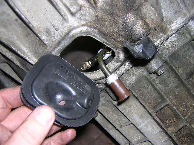
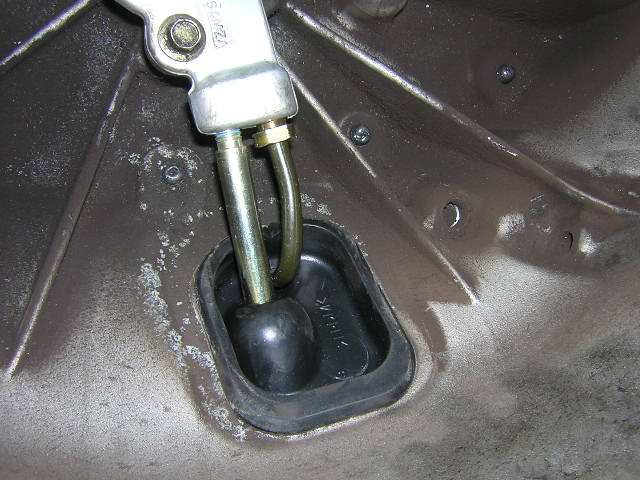
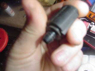
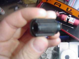
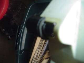
what is the vent do and is there any pictures of this? Is the number listed for the second vent part somewhere?
Never had any resolution to this. Steve at Tousley Ford couldn't come up with any additional vents. As for pictures here you go:
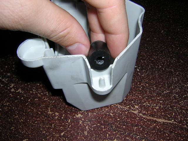
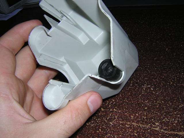
As you can see not much of a vent, more or less something to keep things from plugging up the hole on the case.
-Mike
98 Contour SVT
Toreador Red #49 of 6535 Built on 3/25/97
WR Headers, Borla Cat-Back, Torsen T2 LSD, K&N Short Ram, S-AFC and Focus Shift Tower
85 Camaro
1969 358ci, 97 TA interior, 91 Z28 GrdEfx and Aero Wing 255rwhp
|
|
|
|
|
Joined: Nov 2004
Posts: 139
CEG\'er
|
|
CEG\'er
Joined: Nov 2004
Posts: 139 |
Thanks so much for the help.. I continued reading after i posted those questions and it looks like I am one of the lucky few that are stuck with the only shift cables (LEVEL 3 Cable assys) that can't be fitted to the focus shift tower that I've already purchased (ball end style). Ford has made a real mess with the different combinations of shift tower, clamp ends, shift cables that fit on the different MTX-75 equiped models. There are only a few combinations of parts that will work for the Contour and even then you have to be careful because some parts are no longer offered. This might be old news to alot of people but hopefully it will help having this information linked to this HOW TO. It might make people think twice about upgrading the shift tower all together. If you are one of those people make sure to read over the link below to understand what you are getting into with this mod. Terry Haines MTX-75 Explanation There is another very inexpensive mod for the stock contour shift tower that involves securing the main bolt with saftey wire. I don't have the link at the moment but I found it pretty easy searching the transaxle board. P.S. Anybody want to buy a Focus Shift Tower 
98.5 Black contour // A.K.A. Frankenstein
3L Oval port swap W P&P // SVT UIM, LIM, & Cams
Torsen LSD // Dual Friction // KKM // Poly Mounts // ?Mystery Mod? // Actually Running!
205 hp @ 6500RPM 180 tq @ 4250RPM
|
|
|
|
|
Joined: May 2004
Posts: 636
Veteran CEG\'er
|
|
Veteran CEG\'er
Joined: May 2004
Posts: 636 |
Originally posted by CSVT#49:
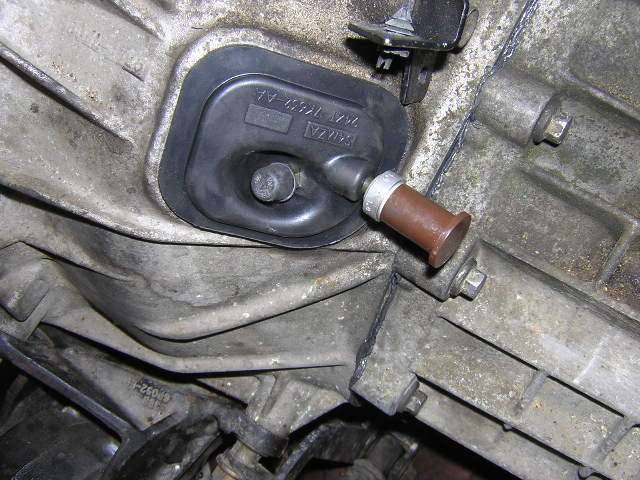
One update on this. Nowhere in this How-To did I mention the rubber vent for the shift tower. The part number is correct (I had gotten it from a previous posting on here), but there is still an additional vent piece that is needed as I discovered. I'm still trying to track down the Ford part number and will post it when I find it.
I know it's been a while but I finally have some closure on this since my brother just received his order of a brand new MTX-75 from CTA Motorsports. The correct part number for the vent is as follows:
XS4R-7L282-AB
Here are some pictures:
 
Could a moderator edit the first post of this how-to, to reflect this change?? In the first post I have it listed as
Originally posted by unisys12:
XS4Z-7L282-AA Vent
It should now read
XS4R-7L282-AB Vent
Thanks.
-Mike
98 Contour SVT
Toreador Red #49 of 6535 Built on 3/25/97
WR Headers, Borla Cat-Back, Torsen T2 LSD, K&N Short Ram, S-AFC and Focus Shift Tower
85 Camaro
1969 358ci, 97 TA interior, 91 Z28 GrdEfx and Aero Wing 255rwhp
|
|
|
|
|
Joined: May 2004
Posts: 636
Veteran CEG\'er
|
|
Veteran CEG\'er
Joined: May 2004
Posts: 636 |
Originally posted by CSVT#49:
It should now read
XS4R-7L282-AB Vent
I found out that this engineering number does not directly correspond to a Ford part number.
I ordered the correct one and found out it's actually the same as the orignal one I gave, but ends in AB instead of AA.
There for the correct part number is XS4Z-7L282-AB
-Mike
98 Contour SVT
Toreador Red #49 of 6535 Built on 3/25/97
WR Headers, Borla Cat-Back, Torsen T2 LSD, K&N Short Ram, S-AFC and Focus Shift Tower
85 Camaro
1969 358ci, 97 TA interior, 91 Z28 GrdEfx and Aero Wing 255rwhp
|
|
|
|
|