• Welcome to the Contour Enthusiasts Group, the best resource for the Ford Contour and Mercury Mystique.

    You can register to join the community.

I/C Rear Lateral (Toe Bars)

Status
Not open for further replies.

CrazyTalkSVT

Veteran CEG'er
Joined
Feb 4, 2008
Messages
856
Location
Minnesota
Just curious who might be on board for a set of the Rear Lateral Toe Bars like I built for my car. The price would be $250.00 + shipping costs for bars just like the ones I made for my car.

If you wanted to upgrade to Delrin Bushings, the price would increase to $285.00 + shipping.

If you want to upgrade to Military Grade Heim joints, the price increases to $635.00 + shipping.

So for Military Grade Heims along with Delrin Bushings the price is $670.00 + shipping.

If you're only interest is in Delrin Bushings, we machine them to size and price accordingly. Typically, the cost is roughly $30.00 for the Delrin to complete one endlink, but there is an additional cost for the inner sleeve which depends on the size bolt for your application.

Here is a copy/paste of the OP:


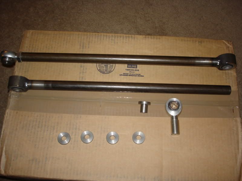
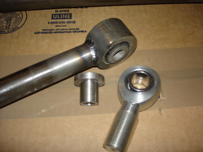
I'll show you what I did for the rear lateral bars. The bars are 1" DOM 3/16" wall. The spindle side is tapped 3/4 - 16 for the heim. I used a 3/4" hole and shank sized heim that is PTFE(Self lubricating teflon) lined. The inner end link was 2" DOM with a 3/8" wall that has been bored for an interference fit for the factory bushings.

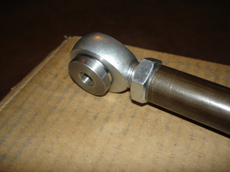
Because the heim is a 3/4" hole which is obviously too big, but the housing itself is physically smaller than factory I made spacers to take up the difference. They get the bolt size back down to the metric factory size as well as take up .25" to align the bar back to straight.

From the factory Ford uses eccentric washers and slotted holes on the inner mounts for toe in and toe out adjustments. Now the adjustment is on the spindle side using the heims threads, but those pesky slotted holes are still on the subframe. So the four machined .25" thick washers you see in the pictures are what align the inner end link to center. So now the chance of the bar slipping in the slotted hole is gone.
bars.jpg


Endlink.jpg


heim.jpg
 
Might be a dumb question as I don't really know the correct terminology, but are these the same rear parts that Bradness was making for people??
 
what's the risk of snapping the inner end link?...I've read in other threads that this has happened in similarily designed bars...
 
The 1"od x 3/16" wall dom is the tube to use.

The weld on "Johnny joint" is one way to go BUT the weld is going to be the weak link in the design. I can't x-ray the thing and I don't want to risk peoples lives on a weld.

I built the same thing except in mine both rod ends are threaded in. One is left hand thread and one is right hand thread. This way you can adjust your toe in without disconnecting anything.

Another change I made was to add a hex nut welded to the shaft so you can turn to adjust it with an open end wrench. (1-1/4")

One rod end is 5/8" bore and you need to re tap the upright to 5/8 nc.
The top end on the rear cross member was changed to 1/2" ID and Arp chrome molly bolts are used. I needed to make square flat washers from flat stock to center the former toe adjust point, from steel flat stock and enlarge the id of the cross member at that point to 1/2" id.

The difference in thickness of the rod end vs. the original arm is made up of Arp hardened washers. They are a little bit of a PITA to get in but they never have to come out again. With this design no specially machined spacers are needed..."one less thing to worry about".:eek:

Over all this set up gives no welds to fail. The rod ends are capable of supporting 23,000 pounds each before they fail and the 1" x 3/16" dom tubing is stronger then the rod ends.

I don't know what anyone considers a good deal but there is about $80 in materials in each arm and about $100 in labor in each.

We are having so much problem with this car in the rear that this solution just made sense. We have torn the rear anti-sway bar brackets loose on three or four occasions and the solution was to get another and reinforce the hell out of it.

Hopefully this won't make the fuse able link now the four bolts that hold the rear cross member to the unibody but I suppose we will find this?

It's hard to tell if the original factory arms are flexing under load or whether the entire sub-frame is squiggling around. We have this thing putting down something like 315 hp on the ground with the Vortec supercharger and it is so much more then very quick to 80 and after that it is like Star Trek switching into warp drive and goes to 130 sooner then you can blink.

(We are in the process of maxi extrude honing the intake, installing a 70mm throttle body and bringing the secondary throttle sizes up to 37mm. I think there is some hp to be picked up there for sure.)

When that happens the rear is darting around like a tractor trailer getting caught in the wind so the main concern at the moment is putting stability into the rear.

There are already BAT springs and struts in the car and maybe the problem is they just need a higher rate? For a front wheel drive car though that shouldn't be the problem? We aren't getting torque steer in the rear, and the rear is just along for the ride.

We'll let you know how it works out. I think these arms are the way to go, without a doubt. They will eliminate the possibility that the factory stamped arms are flexing with our lateral added g-loading back there. These arms are not going to flex.:laugh:


Nevermind. Clearly I made this I/C thread for svtfixer. Hey svtfixer...don't forget to x-ray that hex nut you welded onto the bar...nothing like adding a stress riser right in the middle of the bar.

Don't come on here acting like I have an inferior design. If you used the same heim I did for your design you wouldn't have $80 in material you would have $160 just in heims. It's a PTFE lined Moly heim that has a static load rating of 28,081 lbs. I've talked to people and told them if they wanted to get nutty we could go to a Military grade which is rated at 29,300 lbs but you will pay $232.00 for just one heim.

You can x-ray my TIG welds all day long if you want. I don't really care.


Might be a dumb question as I don't really know the correct terminology, but are these the same rear parts that Bradness was making for people??

Bradness used polyurethane bushings on the inner link (Subframe side). Polyurethane deflects. So, in a sense there is as much or more flex in the end link then ever was in the factory bars. The factory steel encased rubber bushings are tough and deflect less.
If someone wanted to go even stiffer then I would machine some delrin bushings for them and any deflection that had existed before would be gone.


what's the risk of snapping the inner end link?...I've read in other threads that this has happened in similarily designed bars...

The outer heims that snapped were of less a grade. Also, the pictures that I saw showed signs of lack of maintenance.
Any suspension part, whether OEM or aftermarket, is not maintenance free. At a minimum, things like this should be looked over during oil changes for signs of excessive wear and tear.

By no means am I saying you couldn't break these bars. I'm sure if you took a corner at a decent clip and popped the e-brake slinging the car around to a massive curb check they would break. You would probably break a wheel at that point.

What I am saying is with the bars I make you have options based on your driving needs or wants allowing us to tailor them to you. Which is why price is always up in the air depending on your needs or wants.
 
Crazy I've seen your work in person, top notch. I'm interested in a set as well. Keep us posted on the offering and what price range we would be looking at. Thanks!
 
Nevermind. Clearly I made this I/C thread for svtfixer. Hey svtfixer...don't forget to x-ray that hex nut you welded onto the bar...nothing like adding a stress riser right in the middle of the bar.

Don't come on here acting like I have an inferior design. If you used the same heim I did for your design you wouldn't have $80 in material you would have $160 just in heims. It's a PTFE lined Moly heim that has a static load rating of 28,081 lbs. I've talked to people and told them if they wanted to get nutty we could go to a Military grade which is rated at 29,300 lbs but you will pay $232.00 for just one heim.

You can x-ray my TIG welds all day long if you want. I don't really care.


I'm not implying that your work is inferior or the design bad. Not at all. You misunderstood.

I thought we were just having an informal discussion here on this stuff. I have no problem at all on keeping this all to myself and letting you be the King.

Oh, almost forgot... I don't want to x-ray your welds, or anyone else's, that was the point. That's actually for you to do as part of your product representation for liability reasons...and I'm not selling mine here, just describing what I had built for me. Good luck with your sales.

I'll be quite from now on and just let you talk.

Cheers.
:laugh:
 
Bradness used polyurethane bushings on the inner link (Subframe side). Polyurethane deflects. So, in a sense there is as much or more flex in the end link then ever was in the factory bars. The factory steel encased rubber bushings are tough and deflect less.
If someone wanted to go even stiffer then I would machine some delrin bushings for them and any deflection that had existed before would be gone.

Damn, I was hoping these were a different part. I already picked up some of Bradness's off of the classifieds. The ones I have, have rubber bushings, not poly :shrug:

Either way, I wish I would have waited now, as the delrin bushings are what I would really like :blackeye:
 
Damn, I was hoping these were a different part. I already picked up some of Bradness's off of the classifieds. The ones I have, have rubber bushings, not poly :shrug:

Either way, I wish I would have waited now, as the delrin bushings are what I would really like :blackeye:


I don't have a problem machining them to size but they are an interference fit meaning they have to be pressed in. Which would also mean I would need you to mic the endlinks internal dimension. Also would need to know the overall width of the endlink with the bushings in as well as the bushings removed.

As long as you or Bradness think the bars can handle the added stress of no flex I don't have a problem getting you the bushings if you feel it's a good advantage for you.


I should have something together as far as price sometime next week for those interested. :cool:

Great. I would just send you the links, so you would have them in front of you.
 
Do you have powdercoating available? :)


I personally don't care much for powder coating so I blasted, primed, painted, and cleared mine. I think base/clear holds up a bit better, easier to fix or touch up, and if you ever want to change it's easier to get off.

However, it is a cheaper/faster alternative and maybe Mike would be willing to run them. Otherwise, I do have other connections for it.

Got a picture of these bad boys installed?

I'll have to ask my partner. I never took them personally, but I know he shot some after they were installed. I'll ask and get back to ya.
 
Status
Not open for further replies.
Back
Top