• Welcome to the Contour Enthusiasts Group, the best resource for the Ford Contour and Mercury Mystique.

    You can register to join the community.

PCV Routing

Dyoel182

Addicted CEG'er
Joined
Apr 15, 2008
Messages
9,091
Location
North Texas
Does anyone have the actual workshop diagram for the routing on the 2.5, specifically the SVT? I looked at my PCV today and it had what looked like a locking sheath on it plus I couldnt tell where the hose was going. The manual I have is no help nor is the 2000 factory cd that came with the car.
 
Heres what I'm seeing that might make more sense. On the SVT throttle body boot I have the large hose on the right heading to the IAC where I recently added the restrictor cap fitting. On the left side is a smaller hose that looks worn and slips under the plastic cover on the front of the engine that I havent removed yet but will to look at replacing that hose. Now under that I see the rubber boot from what the manual calls the oil/air separator with the PCV valve in the top, but it has the plastic clip hose connected to it instead of vacuum hose like it should. So my question is where is that hose going and why would it have been replaced with this plastic hose at the dealer?
 
I'm not following you but maybe this pic will help.

19-01-08_1001.jpg


The pcv is connected to that short hose with the white cap on it. There is a third hose that goes to the firewall, but I couldn't tell you what that one is for, but it comes off the top and is corrugated plastic.
 
Oh ok so that corrugated plastic hose should be there and I need to leave it alone. I didnt see another hose or white cap when I looked yesterday but I'll see what I see when I'm under the hood next.
 
Now under that I see the rubber boot from what the manual calls the oil/air separator with the PCV valve in the top, but it has the plastic clip hose connected to it instead of vacuum hose like it should. So my question is where is that hose going and why would it have been replaced with this plastic hose at the dealer?
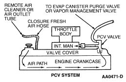
Sounds to me like you're talking about the hose for the EVAP purge control solenoid... should go back to the firewall. However, there should be an additional hose providing vacuum for both the PCV & purge solenoid, as shown in the pic below. The pic shows the 3L design, but gives you the general idea.

AA0471D.gif
 
I'm not following you but maybe this pic will help.

19-01-08_1001.jpg


The pcv is connected to that short hose with the white cap on it. There is a third hose that goes to the firewall, but I couldn't tell you what that one is for, but it comes off the top and is corrugated plastic.
In that pic I have taken off the top piece of the pcv. Where the white cap is what should be connected to the pcv, I had problems getting mine out, so I had to cap the vacuum line temorarily.
 
So the plastic cap on the PCV valve should have two outlets with one corrugated line going back somewhere and another hooking into that metal line via rubber tubing.

However, there should be an additional hose providing vacuum for both the PCV & purge solenoid, as shown in the pic below.

I'm assuming the line in for the left of the TB boot is the fresh air hose then.
 
So the plastic cap on the PCV valve should have two outlets with one corrugated line going back somewhere and another hooking into that metal line via rubber tubing.

I'm assuming the line in for the left of the TB boot is the fresh air hose then.
Correct and correct.
 
So I got a new PCV valve last night and it came with 3 caps, 2 of which have two nipples on them. I assume only one of them will work correctly based on hose size.
 
Last edited:
Back
Top