• Welcome to the Contour Enthusiasts Group, the best resource for the Ford Contour and Mercury Mystique.

    You can register to join the community.

1998 SVT Contour crank, but not starting...

techjunky

New CEG'er
Joined
Sep 20, 2007
Messages
18
Hello everyone, I am new to this forum, but not new to repairing cars in general. I just need some helpful advice.

I just obtained a svt contour from a friend of mine and I am trying to get it up and running.

The starter turns the flywheel when I try and crank the car but I dont get any spark to the plugs.

I have replaced the Crank sensor and the Camshaft Sensor. I have checked to make sure when the key is in the ON position I am getting voltage (6v) to the wire from the #4 20 amp fuse to the coil. However it seems I am not getting anything out of the coil. I have tested the coil using the resistance test on all coils and they check out fine. I have an OBDII reader and I am not getting an DTC codes. So I am kind of stumped. Is there a way to jump start the coil to get spark to my plugs manually? I have checked all the connections a few times and they are all plugged in, except on cannon plug connector near the coil. It looks like a 2 connector plug. I can take pictures if that may help.

Thanks!
 
If you only have 6V at the coil, you have a serious problem right there. It is supposed to be full battery voltage.

The same supply also is used to energize the PCM power relay which, with only 6 V, won't energize and supply power to the PCM which is needed in order to get a spark.

I'll bet that the CEL doesn't come on at normal brightness when you first turn on the key. Of course, your meter might just not be working right....

Steve
 
I am referring to the brown/yellow wire I think? I dont have my manual in front of me. Its the 3rd wire from the left of the plug that looks like a data terminal connector that plugs into the coil pack. This should be 12v? I have a 2002 ford explorer which looks like it uses the same coil pack design. I could look and see what voltage I am getting to the constant wire that goes to the coil on my explorer and see if its the same.

Any other ideas?

The pcm is communicating because my OBDII scanner talks with the PCM.

I am going to purchase a noid light spark plug tester to be sure that its the coil not firing the plugs, but I am almost 100% positive thats the problem. If all else fails, I could run a direct wire from the battery terminal to the coil to make sure its getting 12v. I just want to verify it should be getting a constant 12v so I dont fry anything.

Thanks.
 
Oh, and the CEL light is bright. All lights work etc. I checked at the starter and I get 12v and when cranking I get 11.4V. So I know that portion of the starting system is good.
 
Just for everyone's knowledge here. There should be a 12v constant and a ground wire. Then it looks like the other two communicate with the pcm from what I can tell. I am going to run a wire directly from the battery to the coil cannon connector to provide it with a positive 12v and then try and crank the car and see if that fixes the problem.
 
Ok, so I ran a new wire and I am now getting 12v to the blue/brown wire and I still am not getting any spark coming out of the coil. I tested the coil via the resistance method and it checked out ok... Any other ideas?

I took a meter and hooked the postive side into the the spark plug ignition coil #1 and the negative side to ground. I tried cranking it over while my brother checked to see if he got any voltage out of coil 1... Nadda... The other two wires that tell the coil to fire... Where do they go and how would I go about testing them?
 
Last edited:
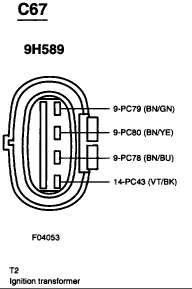
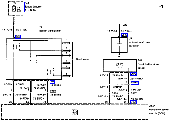
Diagrams to help

Diagrams to help

This might help:) 3 are trigger, one is power, PCM is swtching. Check F4, all wires to PCM and Crank sensor,coil pack ground strap, hopefully PCM survived (your car is not acting any differently after putting 12V on low side of coil.) Note: If your sparks do come back while using voltmeter, it will be ruined (use a spark tester or timing light). I blew my meter testing a TV HV Anode once:eek:

From Alldatadiy.com:

"The ignition system consists of an ignition coil, spark plug wires and spark plugs.

The crankshaft position sensor signal is the basis for ignition timing calculations. The alternating voltage signal from the crankshaft position sensor is digitized by a pulse former within the powertrain control module. This digitized signal is then used to position the closing time of the primary circuit of the ignition coil.

Ignition timing is determined by the powertrain control module in response to engine operating conditions based on stored data tables or maps. Once ignition timing has been determined, the powertrain control module interrupts the current to the primary circuit of the ignition coil thus triggering the ignition spark which is supplied to the cylinders through the spark plug wires and spark plugs.

The ignition coils are triggered by the powertrain control module in pairs (cylinders 1 and 5, cylinders 4 and 3 and cylinders 2 and 6) sending one ignition spark to the firing cylinder and one ignition spark to the corresponding cylinder on the exhaust stroke. This ensures that any unburned fuel residues remaining in the cylinder on the exhaust stroke are re-ignited to provide cleaner exhaust emissions."


coilplug.gif


coil1.gif
 
Last edited:
What does the coil pack ground strap look like? I may be missing this key piece. There is a wire that mounts on the front left bolt of the coil, and has like a plastic grey piece that it goes into and then keeps going somewhere. Any idea if this is the ground strap?
 
What does the coil pack ground strap look like? I may be missing this key piece. There is a wire that mounts on the front left bolt of the coil, and has like a plastic grey piece that it goes into and then keeps going somewhere. Any idea if this is the ground strap?

The coil is grounded by the mounting bolts.

That plastic gray piece is the ignition transformer capacitor shown in the schematic. You can disconnect it while you troubleshoot. FWIW, I've seen several of them short and cause problems on other Ford engines.

Again, you need to fix the supply voltage to the coil.

Steve
 
Ground is on the right front corner of coil pack, easy to lose..Certainly ohm out the capacitor, likely good if "open".
 
Ok, well I am defiantly missing a grounding strap. I will get some 10awg and create a ground wire and ground it to the front right mounting bolt and mount it to the frame and see if this helps. If that doesnt work I will manually trace back the other three wires and make sure they are in good condition.
 
Last edited:
Ok. So I ran a new ground wire from the bolt to the frame and did a continuity test to make sure its a good ground.

I then went ahead and cut open the wiring harness, made a splice in the 12v supply line and tried to back trace it.

There is a plug right by the timing cover where the 4 wires go into an adapter then continue on their way.

I took some pictures to better clarify.

1.JPG

2.JPG

3.JPG


If I go from the Ignition coil plug side and put my meter on numbers 5,6,7,and 8 it seems as though they are touching because I am getting continuity from one wire to the other ones.

Is this normal? I am guessing its not, but I want to make sure. This only happens when the adapter is plugged into the coil. When I take the adapter and unplug it from the coil, each wire has individual continuity.

Also, there is a plug with a yellow boot that I am not able to track down where this is supposed to plug into. Any ideas?

4.JPG


Thanks!
 
Last edited:
I traced the Crankshaft Position sensor, camshaft position sensor, and the ignition coil wires back to the harness that plugs into the pcm and they are all individually wired back to the pcm harness. If someone could test the adapter I posted above with the coil adpater plugged into coil and let me know if you are getting continuity on 5,6,7,8 just like I am I would appreciate it.

At this point it's pointing to the Coil because why would I get contuinuity on all the wires that plug into the coil unless for some reason the coils are internally touching?
 
Last edited:
Ok, really weird. When I plug the ignition coil adapter into the coil I go from 12v to 0v on the brown/green wire immediatly. I unplug the adapter to the coil and I get my 12v again...
 
You get continuity from 6,7,8 to 5 most likely because the coil primary windings are together. Unplug the coil, check if any continuity from spark plug terminal to coil input socket (on the coil itself) Example: plug wire 6 to the Brown/green. There should not be any.

coil1.gif
 
Yah, from 6 to the brown/green wire there isnt any continuity... So everything is checking out. I am stumped as to why the coil is not firing then...

Very WEIRD.

Prolly need a new PCM? I think I may just cut my loses and sell it as is.
 
What I would do next is verify continuity of each wire from coil to PCM plug, and back to the 20Amp fuse, as well as the crank sensor wiring. Also, check for bad fuses under the hood (PCM fuses), and for other unplugged devices like that EGR plug you had found.
 
I have already pinned each one out individually back to the pcm. I did the crank sensor, cam sensor, all wires to the coil... Already checked for bad fuses multiple times using a multimeter and have checked for unplugged items.

The only thing I havent traced is where the 20amp fuse actually goes.

I am still getting low voltage to the coil, which from my understanding of the diagram gets its voltage from the pcm? So maybe the pcm isn't getting enough voltage?

Also, on another note.. I went ahead and unplugged the Mass Airflow sensor and the TB sensor and I still wasnt able to pull any codes with my reader... Shouldn't I be getting DTC for those?
 
Last edited:
Back
Top