• Welcome to the Contour Enthusiasts Group, the best resource for the Ford Contour and Mercury Mystique.

    You can register to join the community.

HKS EVC Boost Controller Question

CSVT#49

Addicted CEG'er
Joined
May 28, 2004
Messages
6,768
Location
Andover, MN
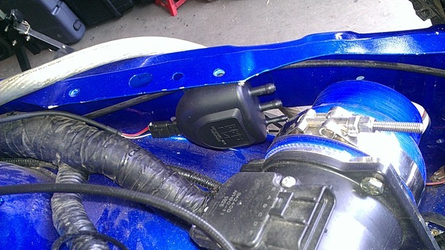
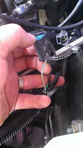
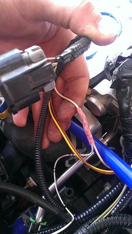
Alright this is a long shot. I've sent an email to the UK HKS office, but I doubt I'll hear back. So I've got the control valve mounted in my car, but I'm now routing the wiring. The HKS instructions are next to worthless for the wiring portion. It shows the harness and all it says for the two wires I cared most about is throttle input signal and speed/rpm input signal (see below).

While I'd love to believe that magically every single cars TPS and VSS signal wires will feed into this thing and work, something tells me that is not the case. Anyone have any experience with these HKS EVC's and what these signal wire inputs are capable of receiving?

Capture-1.jpg
 
Well response from HKS UK, received more than I thought I would and suprisingly the response came the very next day...

Hello Michael,

EVC5 is an older obsolete product that is no longer supported by HKS Europe.

The speed and RPM signals required were 5-12v from traditional speed or RPM sensors. It is not compatible with more modern cars that transmit signals via CAN communication. If your vehicle is off this type then the speed and RPM functions cannot be used unless you have some method of converting the signal.

Unfortunately we have no experience with the Ford range of vehicles either US or UK spec so cannot advise if the speed or RPM function of the EVC can be used with you particular vehicle.

HKS is a Japanese company and we have vehicle data for Japanese brand, JDM spec cars only.

Please note for USA spec vehicles or if you are in the USA you must contact www.motovicitly.com as they are the HKS Distributor for that region.

HKS Europe is the Distributor for Europe, Russia and South Africa only at this time. These are the only regions we support.

I have an email into Motovicity to see if they have any further insight.
 
Last edited:
well tps is a 5v signal. i would think just to splice into the signal wire on it.
rpm would be an AC voltage signal so probably an output rpm signal wire from the ecu such as for the tach?

thats about all i can say, maybe you already knew that. good luck
 
Yup I knew what was up for the TPS. However I dont want RPM, I could just grab that off of the MSD DIS4 as it has a dedicated tach output for such devices. I want actual vehicle speed.

I'm going to base my boost map off of throttle and mph so that I can keep boost low down low and higher as I get up in the gears. However when I'm cruising at half throttle at highway speeds I don't want to be going crazy.

So as of right now I already have tapped into the harness for the TPS. I'm working on tapping into the VSS. I figure worse case it doesn't work and I have to rewire it.
 
I already wired it. Hooked it up to the VSS white/blue signal wire just after the sensor on the vehicle harness side. Harness is all running into the cabin so now I just need to hook up ignition power and a ground and away we go.

Next up vacuum pump.
 
Last edited:
One would hope the factory service manual is correct, which is where I determined what wire to use ;)

Sent from my ADR6425LVW using Tapatalk
 
lol. for sure. i love alldata. i use it free since im doing to automotive technology program at the community college here. and taking high performace and another dyno tuning class this summer. ASE master tech certificate here i come!

anyways glad the build is coming along:D
 
Just to update this thread for future searches since not everyone will look at my build thread. Bolt I used to mount the valve already there from the mounting of the SVT air inlet rubber piece. The bracket that comes with the valve only requires one bolt.

Pics...

54kl.jpg


9t3m.jpg
yekf.jpg
 
Also just a follow up note for people. In my installation I'm running these signal wires along side my battery cable that's coming from the trunk for the remote mount battery. Because of this I've opted to use a "twisted pair" strategy for the signal wires to avoid signal interference from the battery cable. This is similar to that of the cam and crank sensor wiring if you've messed with that. Basically it's twisting each signal wire with a ground wire.
 
Back
Top