
alwayssideways
CEG'er
I have been a EO owner for just a few months now. But my car has the harness that is just disintegrating.
I originally tried to repair the harness. The more I dug into it the more I didnt like what I was finding. So I decided that I was going to figure out what it takes to swap the E1 to E0 harness.
Well I figured it out. So since I have been getting some good information from this site, I thought that I would give something back. So this is what I did. So if you try this please do so at your own risk.
Also PLEASE PLEASE PLEASE read through the how to first before doing anything.
I just want to point a few things out in terms of words I use to describe parts of the harness.
Square harness = other main connection held in with a 10mm bolt that is located on the drivers side strut tower
E0 - pre 1998.5 harness
E1 - 1998.5 and +
jump = connect
With that being said. Here are some materials that I used
Stock E0 harness
Stock E1 harness
** optional**other duratec wiring harness ( I used a 99 auto cougar)
pick set
heat shrink
wire strippers
needlenose pliers
soldiering gun and soldier
Heat gun or other tool to heat the shrink tubing
Once again I focused strictly on the square connector and not the ecu end of the harness. Also when I connected the wires (jumped) I left the wires I was eliminating in the harness to keep it intact
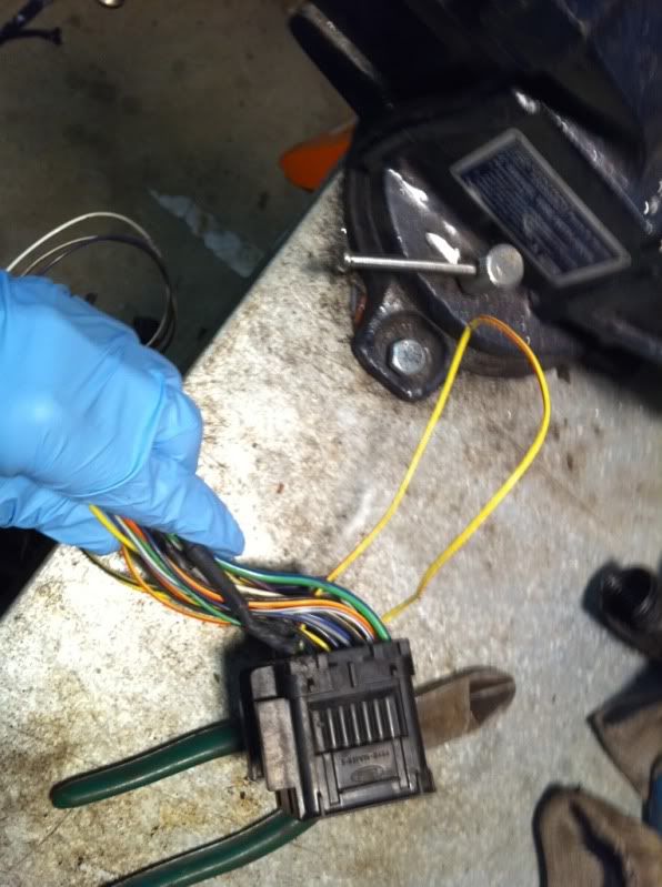
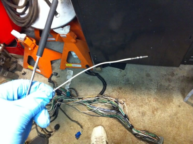
Prep: on the E1 harness clean off the loom and tape for about 1' from the square harness. You can leave the rest alone.
Step 1
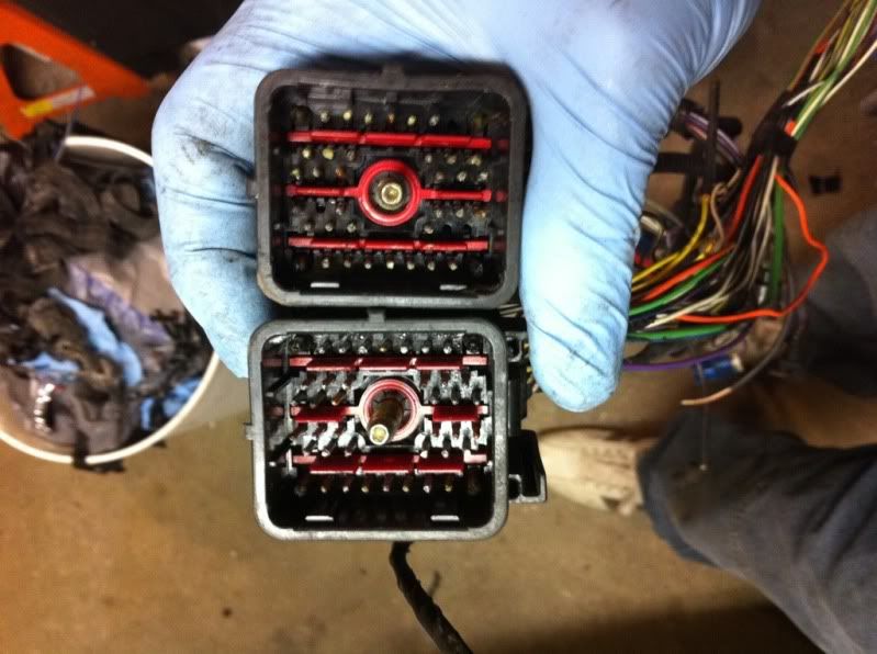
I put the E1 and E0 square connector right next to each other(looking at the pins) I noticed that the EO has more pins than the E1. We have to make the E1 square harness look like the EO. This is why I suggest getting another duratec harness as parts. I used the pins from my parts harness so I could keep a (if you want to call it this) working stock E0 harness.
Step 2
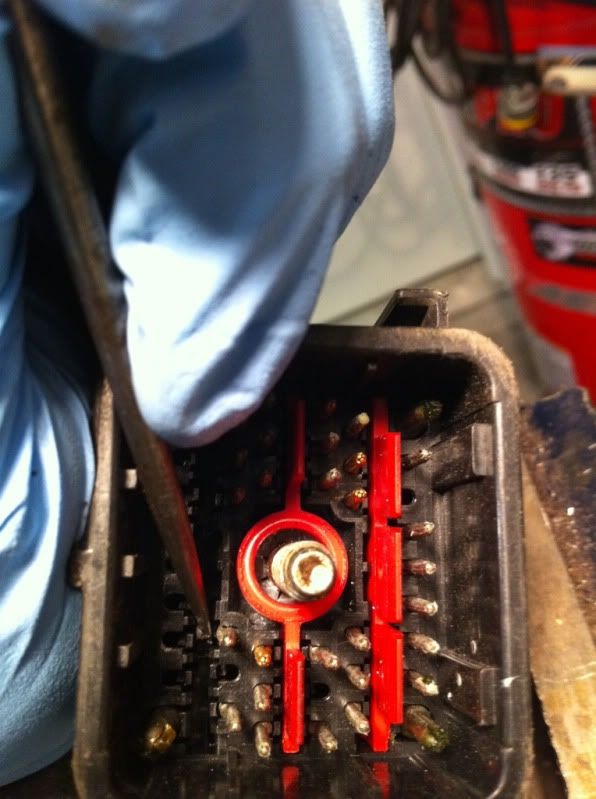
Now look at the back of the square harness you will see that the wires are labeled with numbers. The numbers match on both harnesses. So when I refer to wire # or pin #. I am referring to the number slot on the square harness.
Step 3
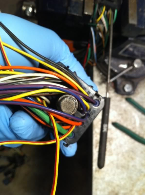
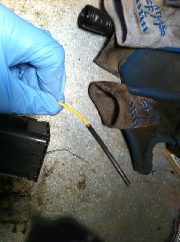
We need to put a pin in slot #41. This is done by locating #41 on the E1 harness. Here I used the straight pick. I put the pick in the dimple where #41 is suppose to be. I then pushed the pick into the harness. You will feel the pick go through and it will poke out a plastic needle out the other side of the harness.
Step 4
Flip the harness you just put the pick through and locate the slot on this side of the harness. There will be a red retainer clip located next to where its coming through. Use the needle nose pliers and gently pull out th red retainer clip. After the red clip is out you should be able to see the plastic needle coming out of the new hole you punched in the previous step. I used the pliers to get the plastic needle out. You might need to gently pull back the plastic retainer clip for the pin which is touching the plastic needle.
Step 5
Put a new pin in the hole you just cleared(#41), and make sure that you have about 6"-8" of wire coming off the new pin. Make sure the pin locks in place. I replace the red retainer each time I put in a new pin.
Step 6
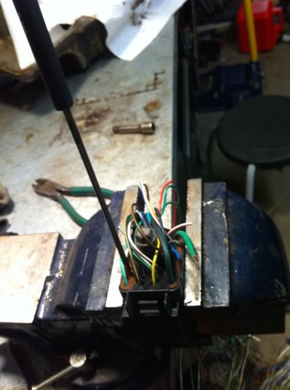
Locate wire #28 on the E1 harness and connect it to the pin you just put in (#41). I did this with soldier and heat shrink.
Step 7
Next find #36 and #7 on the E1 harness. Here you will see #7 has a fusable link on it. You are going to want to cut it off. But make sure you save enough wire on both the fusable link and the harness side of the wire. You will be reusing the Fusable link
Step 8
Once again on the E1 harness. Connect #6 to #35.
Step 9
Get ready to add more pins.
We need to add pins on the E1 harness. We need to add pins #14, #15, #17. 3 total new pins
Step 10
Take the fuseable link that we cut off before and attach it to #14
Step 11
Connect the rest of the new pins. (#15 to #17)
Once again please attempt at your own risk. I assume no responsibility for what you do to your car. I am willing to answer questions if needed. Please shoot me a pm. Also I have some extra pins laying around that I could send people if they need(that way you dont need to get a parts harness) I hope this helps people. I know it made me feel better about the car knowing I have decent wiring in the car. If you feel compelled and this really helps. I do take donations. My paypal is boostint2@yahoo.com. I will post pics here shortly.
I originally tried to repair the harness. The more I dug into it the more I didnt like what I was finding. So I decided that I was going to figure out what it takes to swap the E1 to E0 harness.
Well I figured it out. So since I have been getting some good information from this site, I thought that I would give something back. So this is what I did. So if you try this please do so at your own risk.
Also PLEASE PLEASE PLEASE read through the how to first before doing anything.
I just want to point a few things out in terms of words I use to describe parts of the harness.
Square harness = other main connection held in with a 10mm bolt that is located on the drivers side strut tower
E0 - pre 1998.5 harness
E1 - 1998.5 and +
jump = connect
With that being said. Here are some materials that I used
Stock E0 harness
Stock E1 harness
** optional**other duratec wiring harness ( I used a 99 auto cougar)
pick set
heat shrink
wire strippers
needlenose pliers
soldiering gun and soldier
Heat gun or other tool to heat the shrink tubing
Once again I focused strictly on the square connector and not the ecu end of the harness. Also when I connected the wires (jumped) I left the wires I was eliminating in the harness to keep it intact
Prep: on the E1 harness clean off the loom and tape for about 1' from the square harness. You can leave the rest alone.
Step 1
I put the E1 and E0 square connector right next to each other(looking at the pins) I noticed that the EO has more pins than the E1. We have to make the E1 square harness look like the EO. This is why I suggest getting another duratec harness as parts. I used the pins from my parts harness so I could keep a (if you want to call it this) working stock E0 harness.
Step 2
Now look at the back of the square harness you will see that the wires are labeled with numbers. The numbers match on both harnesses. So when I refer to wire # or pin #. I am referring to the number slot on the square harness.
Step 3
We need to put a pin in slot #41. This is done by locating #41 on the E1 harness. Here I used the straight pick. I put the pick in the dimple where #41 is suppose to be. I then pushed the pick into the harness. You will feel the pick go through and it will poke out a plastic needle out the other side of the harness.
Step 4
Flip the harness you just put the pick through and locate the slot on this side of the harness. There will be a red retainer clip located next to where its coming through. Use the needle nose pliers and gently pull out th red retainer clip. After the red clip is out you should be able to see the plastic needle coming out of the new hole you punched in the previous step. I used the pliers to get the plastic needle out. You might need to gently pull back the plastic retainer clip for the pin which is touching the plastic needle.
Step 5
Put a new pin in the hole you just cleared(#41), and make sure that you have about 6"-8" of wire coming off the new pin. Make sure the pin locks in place. I replace the red retainer each time I put in a new pin.
Step 6
Locate wire #28 on the E1 harness and connect it to the pin you just put in (#41). I did this with soldier and heat shrink.
Step 7
Next find #36 and #7 on the E1 harness. Here you will see #7 has a fusable link on it. You are going to want to cut it off. But make sure you save enough wire on both the fusable link and the harness side of the wire. You will be reusing the Fusable link
Step 8
Once again on the E1 harness. Connect #6 to #35.
Step 9
Get ready to add more pins.
We need to add pins on the E1 harness. We need to add pins #14, #15, #17. 3 total new pins
Step 10
Take the fuseable link that we cut off before and attach it to #14
Step 11
Connect the rest of the new pins. (#15 to #17)
Once again please attempt at your own risk. I assume no responsibility for what you do to your car. I am willing to answer questions if needed. Please shoot me a pm. Also I have some extra pins laying around that I could send people if they need(that way you dont need to get a parts harness) I hope this helps people. I know it made me feel better about the car knowing I have decent wiring in the car. If you feel compelled and this really helps. I do take donations. My paypal is boostint2@yahoo.com. I will post pics here shortly.